0020213394_05 Installation and maintenance instructions
19
Additives intended to remain permanently in the
installation
–
Adey MC1+
–
Fernox F1
–
Fernox F2
–
Sentinel X 100
–
Sentinel X 200
Additives for frost protection intended to remain
permanently in the installation
–
Adey MC ZERO
–
Fernox Antifreeze Alphi 11
–
Sentinel X 500
▶
If you have used the above-mentioned additives, inform
the end user about the measures that are required.
▶
Inform the end user about the measures required for frost
protection.
7.1.2
Filling and purging the heating installation
1.
Open all of the thermostatic valves on the heating in-
stallation and, if required, all other isolation valves.
2.
Check all of the connections and the entire heating
installation for leaks.
1
3.
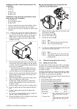
Push the white switching lever
(1)
on the motor head
of the diverter valve until it engages in its mid-position
in order to move the heating/cylinder charging diverter
valve into the mid-position.
◁
Both valves are open and the filling procedure is
improved since the air in the system can escape.
4.
Connect a filling hose to the heating water supply.
5.
Remove the screw cap from the filling and drain valve
for the heating circuit and fasten the free end of the
filling hose to the valve.
6.
Open the filling and drain valve for the heating circuit.
7.
Open the heating water supply slowly.
8.
Fill with water until the manometer (on-site) shows
that the heating installation has reached a pressure
of approx. 1.5 bar.
9.
Close the filling and drain valve for the heating circuit.
10.
Purge the heating circuit at the locations provided for
this.
11.
Purge the heating pump using the heating pump's
drain screw.
12.
Then check the heating installation pressure again (if
required, repeat the filling procedure).
13.
Remove the filling hose from the filling and drain valve
and screw the screw cap back on.
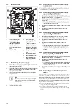
Moving the heating/cylinder charging diverter
valve into the starting position
45°
A
B
C
D
14.
Remove the power supply cable from the motor head
of the diverter valve
(A)
.
15.
Push the locking lever
(B)
.
16.
Turn the motor head 45°
(C)
.
17.
Remove the motor head
(D)
.
Note
This moves the spring in the valve body
back into the starting position.
18.
Turn the motor head back towards the valve body and
reconnect the power supply cable.
Note
The white switch lever on the motor head
of the diverter valve should now be in the
starting position.
7.2
Filling and purging the brine circuit
7.2.1
Mixing the brine fluid
The brine fluid consists of water mixed with a concentrated
antifreeze. The brine fluids that may be used differ greatly
from region to region. For more information, contact the re-
sponsible authorities.
Only the brine fluids named here are authorised by Vaillant
for operating the heat pump; operating the heat pump with
other fluids, e.g. pure water is not permitted.
Alternatively, suitable ready-mixed fluids for heat pumps can
be ordered from Vaillant.
▶
Use a sufficiently large mixing container.
▶
Carefully mix ethylene glycol with water.
Approved environment source
Ground
/groundwater
module
Air/brine
collector
Brine content
30% vol.
44% vol.
Water content
70% vol.
56% vol.
* Cloud point
** Cold protection
Above this temperature, the first ice
crystals start to form in the brine
fluid.
At this temperature, half of the fluid
volume has frozen; there is slush
ice.


