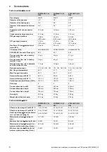
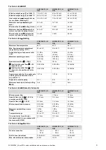
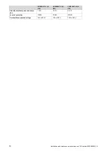


22
Installation and maintenance instructions ecoTEC sustain 0020253094_05
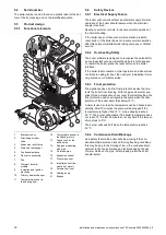
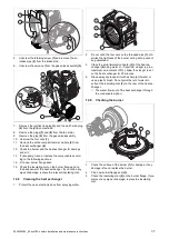
7.9
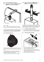
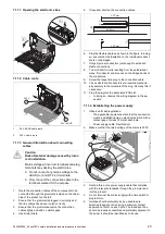
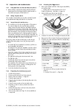
Installing the discharge pipe on the
expansion relief valve
1
1.
Ensure that the pipeline is visible.
2.
Connect the expansion relief valve
(1)
.
3.
The pipe must have a continuous fall and be routed
to a position so that any discharge of water, possibly
boiling, or steam cannot create any danger to persons,
damage to property or external electrical components
and wiring.
◁
The components must be set up in such a way that
you can see the water flowing out.
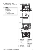
7.10
Flue installation
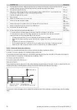
7.10.1 Installing and connecting the air/flue pipe
1.
You can find out which air/flue pipes may be used by
consulting the enclosed set-up instructions for the
air/flue system.
Condition
: Installation in damp rooms
▶
You must connect the product to a room-sealed air/flue
system. The combustion air must not be taken from the
installation site.
2.
Install the air/flue pipe as described in the set-up in-
structions.
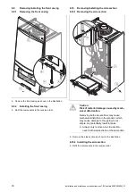
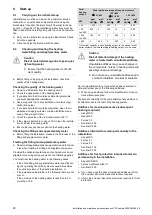
7.10.2 Replacing the connector for the air/flue pipe
as required
1.
Replace the connector for the air/flue pipe as required.
The product-specific standard equipment is listed under
Technical data.
2.
Remove the connection piece for the air/flue pipe
–
this
is installed at the factory. (
3.
If required, install the connection piece for the air/flue
pipe, 80/125 mm diameter. (
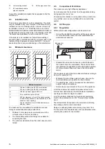
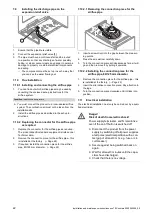
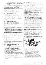
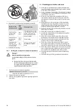
7.10.2.1 Removing the connection piece for the
air/flue pipe
A
B
C
1.
Insert a screwdriver into the gap between the measur-
ing points.
2.
Press the screwdriver carefully down.
3.
Turn the connection piece anticlockwise as far as it will
go and then remove it by pulling it upwards.
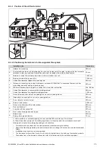
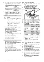
7.10.2.2 Installing the connection piece for the
air/flue pipe, 80/125 mm diameter
1.
Remove the connection piece for the air/flue pipe
–
this
is installed at the factory. (
2.
Insert the alternative connection piece. Pay attention to
the lugs.
3.
Turn the connection piece clockwise until it clicks into
position.
7.11
Electrical installation
The electrical installation must only be carried out by a quali-
fied electrician.
Danger!
Risk of death from electric shock!
Power supply terminals L and N remain live
even if the on/off button is switched off:
▶
Disconnect the product from the power
supply by switching off all power supplies
at all poles (electrical partition with a con-
tact gap of at least 3 mm, e.g. fuse or cir-
cuit breaker).
▶
Secure against being switched back on
again.
▶
Wait for at least 3 minutes until the capa-
citors have discharged.
▶
Check that there is no voltage.
Summary of Contents for ecoTEC sustain 24
Page 1: ...en Installation and maintenance instructions ecoTEC sustain 24 28 34 0020253094_05 04 11 2020...
Page 61: ......
Page 62: ......
Page 63: ......


