0020230531_06 ecoFIT pure Installation and maintenance instructions
27
1
1
1.
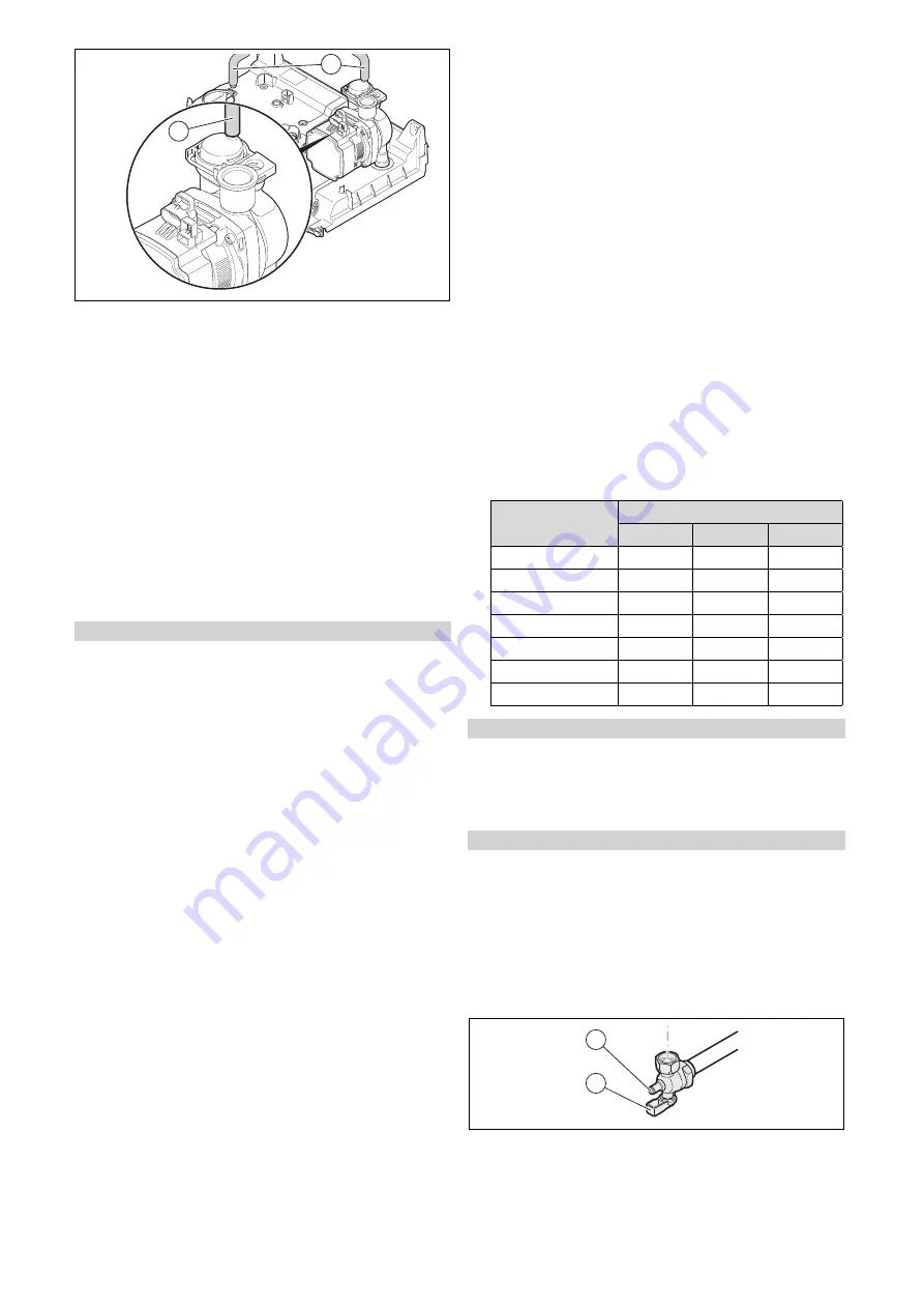
Check the silicone hose connection
(1)
between the
pump's automatic air vent and the hydraulic console.
2.
Fill with water until the required filling pressure is
reached.
–
Recommended filling pressure: 1 to 1.5 bar
◁
The heating and domestic hot water functions can-
not be activated.
◁
The pressure value flashes in the display until a
pressure of 0.05 MPa (0.5 bar) or higher has been
reached.
◁
An automatic air vent function is activated if the
pressure exceeds 0.05 MPa (0.5 bar) for longer than
15 seconds.
3.
Purge each radiator until the water escapes normally,
and then retighten the installation's purging valves.
4.
Check that all connections are leak-tight.
Condition
: If the noise persists in the boiler
▶
Purge the product again by activating check programme
P.00
.
9.8
Filling the domestic hot water circuit
1.
Open the water tap to fill the domestic hot water circuit.
2.
Close the water tap once the appropriate volume of
water has flowed out.
◁
The domestic hot water circuit is filled.
3.
Check all connections and the entire system for leak-
tightness.
9.9
Checking the gas setting
Only a qualified competent person is authorised to imple-
ment the settings on the gas valve assembly.
Each destroyed seal must be replaced.
The CO
₂
adjusting screw must be sealed.
Never modify the factory setting of the gas pressure regu-
lator of the gas valve assembly.
9.9.1
Checking the air/flue pipe/flue gas
recirculation
1.
Check the flue gas installation is intact in accordance
with the latest gas safe technical bulletin and informa-
tion supplied in the installation instructions.
2.
For extended flue gas installations check for flue gas
recirculation using the air analysis point.
3.
Use a flue gas analyser.
4.
If you discover unusual levels of CO or CO
2
in the sup-
ply air, search for the leak in the flue system or for signs
of flue gas recirculation.
5.
Eliminate the damage properly.
6.
Check again whether the supply air contains any unusal
levels of CO or CO
2
.
7.
If you cannot eliminate the damage, do not start up the
product.
9.9.2
Checking the gas flow rate
The gas flow rate has been set during production and does
not require adjustment. With the front casing fitted check the
gas flow rate of the boiler as follows:
▶
Start up the product with the check programme
P.01
.
▶
In addition, ensure that maximum heat can be dissipated
into the heating system by turning up the room thermo-
stat.
▶
Wait at least 5 minutes until the boiler has reached its
operating temperature.
▶
Ensure that all other gas appliances in the property are
turned off.
▶
Measure the gas flow rate at the gas meter.
▶
Compare the measured values with the corresponding
values in the table.
Qnw from the data
plate
H gas in m
³
/h
Nom.
+5%
−
10%
15.3
1.62
1.70
1.46
18.4
1.95
2.05
1.76
24.7
2.61
2.74
2.35
25.7
2.72
2.86
2.45
28.6
3.03
3.18
2.73
30.6
3.24
3.40
2.92
35.7
3.78
3.97
3.40
Condition
: Gas flow rate not in the permissible range
▶
Check all of the piping and ensure that the gas flow rates
are correct.
▶
Only put the product into operation once the gas flow
rates have been corrected.
Condition
: Gas flow rate in the permissible range
▶
End the check programme
P.01
.
▶
Allow the boiler to cool down by allowing pump overrun to
operate for a minimum of 2 minutes.
▶
Record the boiler maximum gas flow rate onto the
Benchmark gas boiler commissioning checklist.
9.9.3
Checking the gas connection pressure (gas
flow pressure)
1
2
1.
Ensure that the gas inlet working pressure can be
obtained with all other gas appliances in the property
working.
2.
Close the gas stopcock
(1)
.


