background image

Installation 5

0020233500_01 auroCOMPACT Installation and maintenance instructions

17

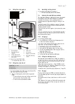
5.7.2

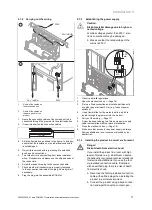
Carrying out the wiring

24V / eBUS

230V

24V / eBUS

230V

2

1

1

Route of the cables on
the electronics box

2

Route of the cables on
the back panel of the
product

1.

Route the connection cables of the component to be
connected through the grommet to the electronics box.

2.

If required, shorten the connection cables.

30 mm

3.

Strip the flexible line as shown in the figure. In doing so,
ensure that the insulation on the individual conductors
is not damaged.

4.

Only strip inner conductors just enough to establish
good, sound connections.

5.

To avoid short circuits resulting from loose individual
wires, fit conductor end sleeves on the stripped ends of
the conductors.

6.

Screw the respective plug to the connection cable.

7.

Check whether all conductors are properly fastened
to the connection terminals of the plug. Remedy this if
necessary.

8.

Plug the plug into the associated PCB slot.

5.7.3

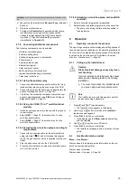
Establishing the power supply

Caution.
Risk of material damage due to high con-
nected voltage.

At mains voltages greater than 253 V, elec-
tronic components may be damaged.

Make sure that the rated voltage of the
mains is 230 V.

≤ 30

mm

1.

Observe all valid regulations.

2.

Open the electronics box. (

Page 16)

3.

Set up a fixed connection and install a partition with

a contact gap of at least 3 mm (e.g. fuses or power
switches).

4.

Use a flexible line for the mains feed line, which is

routed through the grommet into the product.

5.

Carry out the wiring. (

Page 17)

6.

Screw the supplied plug to a three-core power supply

cable that complies with the relevant standards.

7.

Close the electronics box. (

Page 16)

8.

Make sure that access to the power supply is always

freely available and is not covered or blocked by an
obstruction.

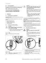
5.7.4

Installing the product in a moist environment

Danger!
Risk of death from electric shock!

If you install the product in a room with high
levels of moisture, e.g. a bathroom, observe
the nationally recognised technical standards
for electrical installations. If you use the fact-
ory-installed connection cable, if installed,
with an earthed plug, there is a risk of death
from electric shock.

Never use the factory-installed connection
cable with earthed plug when installing the
product in a moist environment.

Connect the product using a fixed connec-
tion and a partition with a contact open-

Summary of Contents for 0010020257

Page 1: ...llation and maintenance instructions auroCOMPACT VSC D 4 DE Publisher manufacturer Vaillant GmbH Berghauser Str 40 D 42859 Remscheid Tel 49 21 91 18 0 Fax 49 21 91 18 2810 info vaillant de www vaillan...

Page 2: ...ming a gas family check 22 7 10 Using check programmes 23 7 11 Checking and treating the heating water filling and supplementary water 24 7 12 Reading off the filling pressure 24 7 13 Preventing low w...

Page 3: ...Decommissioning 41 11 1 Decommissioning the product 41 12 Recycling and disposal 41 13 Customer service 41 13 1 Customer service 41 Appendix 42 A Pipe lengths in the B23P installation 42 B Installer...

Page 4: ...operating installation and servicing instructions for the product and any other system compon ents installing and fitting the product in accord ance with the product and system approval compliance wi...

Page 5: ...smell flue gas in the prop erty Open all accessible doors and windows fully to provide ventilation Switch off the product Check the flue gas routes in the product and the flue gas diversions 1 3 6 Ris...

Page 6: ...st or similar substances may lead to corrosion on the product and in the flue system Ensure that the supply of combustion air is always free of fluorine chlorine sulphur dust etc Ensure that no chemic...

Page 7: ...ory Condensing techno logy Efficiency class of the boiler in accord ance with EC Directive 92 42 EEC Type e g C13 Permissible flue gas connections PMS e g 3 bar 0 3 MPa Maximum water pressure in heati...

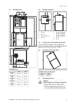
Page 8: ...rcuit 17 Filling with solar fluid or purging 18 Heating circuit pressure sensor 19 Plate heat exchanger 20 Heating expansion vessel 21 Electronics PCB for the gas generator control process 4 Set up 4...

Page 9: ...20 mm 300 mm D 600 mm E 165 mm air flue pipe 60 100 mm diameter 275 mm air flue pipe 80 125 mm diameter F 40 mm G 70 mm 4 5 Clearance from combustible components It is not necessary to maintain a clea...

Page 10: ...move the insulating elements 3 and 5 Undo the nut 9 on the domestic hot water cylinder Remove the upper hose from the condensate trap Remove the power plug from the cylinder temperature sensor Remove...

Page 11: ...nated cleaning agents paint adhesives ammonia compounds or other similar substances are stored or used Take the weight of the unit including the water content into account Look up information on this...

Page 12: ...connection pipes if they have not yet been connected to the product Caution Risk of material damage due to heat trans fer during soldering Only solder connectors if the connectors are not yet screwed...

Page 13: ...on vessel is insufficient for the installation install an additional expansion vessel connected as close to the product as pos sible in the heating return 2 Install an expansion relief valve and a sto...

Page 14: ...be used without being connected to the solar cir cuit In this case set diagnostics code d 200 to 1 Ensure that the heat insulation of the lines is sufficient to prevent excessive heat losses The outsi...

Page 15: ...eten tion vessel accessory 20 m 20 m Note If there is insufficient solar fluid in the installa tion the pump may cause a noise If required fill the unit 5 5 4 Solar connection Note The unit has the fo...

Page 16: ...onnected to a cascade flue gas system that is being used by other units Observe the applicable international national and local regulations for flue gas systems in particular for installa tions in liv...

Page 17: ...greater than 253 V elec tronic components may be damaged Make sure that the rated voltage of the mains is 230 V 30 mm 1 Observe all valid regulations 2 Open the electronics box Page 16 3 Set up a fixe...

Page 18: ...allation instruc tions for the solar collector 2 Route the cable for the solar sensor 1 from the col lector to the product s solar plug 1 2 3 Connect the cable for the solar sensor 1 to the solar plug...

Page 19: ...the external button using terminals 1 0 and 6 functional drawing on the X41 edge connector which is supplied with the con troller 2 Plug the edge connector into the PCB slot X41 3 Press the external...

Page 20: ...a reduction in the ser vice life of the product If the product design does not match the local gas group malfunctions will occur or you will have to replace product components prema turely Before you...

Page 21: ...ive Confirm that you want to navigate to the next point by press ing Next If you do not confirm the launch of the installation assistant it is closed 10 seconds after you switch on the unit and the ba...

Page 22: ...y time by call ing it up in the menu Menu Installer level Start inst assistant 7 8 Calling up appliance config and diagnostics menu You can recheck and reset the most important system para meters usin...

Page 23: ...ins with the hot water circuit short heating circuit 7 minutes and 30 seconds and ends with the heating circuit 2 minutes and 30 seconds 1 x Cancel End purge programme Note The purge programme runs fo...

Page 24: ...dness at specific system volume 1 20 l kW 20 l kW 50 l kW 50 l kW kW dH mol m dH mol m dH mol m 50 16 8 3 11 2 2 0 11 0 02 50 to 200 11 2 2 8 4 1 5 0 11 0 02 200 to 600 8 4 1 5 0 11 0 02 0 11 0 02 600...

Page 25: ...ntil water flows out of the purging valve without bubbles 10 Purge all other radiators until the entire heating system has been filled with water 11 Close all purging valves 12 Fill with water until t...

Page 26: ...ure gauge 10 Tighten the screw on the measuring nipple 1 11 Open the gas isolator cock 12 Check the measuring nipple for gas tightness Conditions Gas connection pressure not in the permissible range C...

Page 27: ...tightly 7 17 1 Checking the heating mode 1 Make sure that there is a heat requirement E g using settings on the system control or cooling the buffer cylinder Note Alternatively you can use the servic...

Page 28: ...the time function element You can use diagnostics code D 002 to set the maximum burner anti cycling time default setting 20 min The effective burner anti cycling times with respect to the target flow...

Page 29: ...itching off the speed regulation and setting the pump output to a fixed value 8 8 1 Remaining feed head pump 8 8 1 1 Pump curve for 14 kW 60 70 50 40 30 20 10 0 500 1000 1500 A B 2 3 1 5 4 1 Bypass cl...

Page 30: ...s required 8 11 Handing the product over to the end user 1 When you have finished the installation attach the sticker supplied 835593 to the front of the product in the user s language 2 Explain to th...

Page 31: ...ined with the exclusive use of original spare parts are decisive factors in ensuring smooth opera tion and long working life for the product We recommend taking out an inspection or maintenance contra...

Page 32: ...tests Menu Installer level Test programs Electronics self test You can use the electronics self test to check the PCB in advance 9 6 Removing the compact thermal module Note The compact thermal modul...

Page 33: ...changer 1 Protect the folded down electronics box against sprayed water 1 2 3 4 2 The four nuts on the threaded pins 4 must never be loosened or tightened 3 Clean the heating coil 2 on the heat exchan...

Page 34: ...casing Page 11 3 Move the electronics box into the upper position Page 11 4 Connect a hose to the drain cock 1 and guide the free end of the hose to a suitable outflow location 5 Open the drain cock...

Page 35: ...he water 2 Unscrew the magnesium protection anode 1 from the cylinder and check the extent to which it has corroded 3 If the anode is more than 60 worn replace it 4 Clean the domestic hot water cylind...

Page 36: ...roduct is in Comfort protection mode The product con tinues to run with restricted comfort after it has detected a fault To establish whether or not a component is defective read the fault memory Page...

Page 37: ...s on the burner 1 3 Remove the burner 4 Fit the new burner with a new seal 5 Ensure that the recesses on the seal and burner are aligned with the sight glass on the burner door 6 Install the compact t...

Page 38: ...mak ing unauthorised settings Never modify the factory setting of the gas pressure regulator of the gas valve Note Some products are fitted with gas valves that do not have a gas pressure regulator N...

Page 39: ...he under side of the gas restrictor Caution Risk of material damage to the product Lubricant can block function related channels in the Venturi Do not use lubricant when installing the gas restrictor...

Page 40: ...go 16 Make sure that the brackets are seated correctly on the flow and return connections 17 Install the compact thermal module Page 34 18 Fill and purge the product and if necessary the heating insta...

Page 41: ...t language set ting is English Select the required language Confirm the setting by pressing OK Set the Device Specific Number D 093 Confirm your setting The electronics are now set to the product type...

Page 42: ...ly corresponds to the maximum permitted flue pipe length without any elbows If elbows are used the maximum pipe length must be reduced in accordance with the dynamic flow char acteristics of the elbow...

Page 43: ...g Language DHW temperature Back Select Target flow temp Appliance config Language DHW temperature Back Select Target flow temp Appliance config Language DHW temperature Back Select Appliance config Te...

Page 44: ...26 Auxiliary relay Cirkulation pump Back D 027 Zubeh rrelais 1 externe Pumpe Cancel OK D 027 Accessory relay 1 Cirkulation pump Back D 028 Zubeh rrelais 2 externe Pumpe Cancel OK D 028 Accessory relay...

Page 45: ...ciency pump Target value of internal high efficiency pump in Pos sible settings 0 Auto 1 53 2 60 3 70 4 85 5 100 6 Auto proKlima 7 Fixed KfW 8 Auto pump boost 0 Auto D 015 Actual pump speed high effic...

Page 46: ...stable D 040 Heating flow temperature Actual value in C Not ad justable D 041 Return temperature Actual value in C Not ad justable D 044 Digitised ionisation value Display field 0 to 1020 800 no flame...

Page 47: ...0 No 1 Yes D 098 Value of coding resistors for gas group and output range Display xx yy xx Coding resistor 1 in cable harness for output range 08 Up to 25 kW 09 up to 30 kW 10 up to 34 kW yy Coding re...

Page 48: ...mum heat input If the gas connection pressure is not within the specified range carry out maintenance work X X 5 Check the CO content the air ratio of the product and if necessary adjust it Keep a rec...

Page 49: ...Burner ignition S 04 Heating mode Burner on S 05 Heating mode Pump fan overrun S 06 Heating mode Fan overrun S 07 Heating mode Pump overrun S 08 Heating mode Remaining burner anti cycling time S 09 He...

Page 50: ...harness NTC defective F 02 Separation of the cylinder charging sensor in the plate heat exchanger outlet NTC defective NTC cable defective defective plug connection on NTC F 03 Cylinder sensor fault N...

Page 51: ...connected or incorrectly connected F 53 Mass flow sensor fault Gas flow pressure too low filter under Venturi filter cap wet or blocked mass flow sensor defective internal pressure measuring point in...

Page 52: ...Safety thermostat when underfloor heating is switched on Setting the target heating value F 90 Fault No communication between SMU and BMU Interruption between BMU and SMU faulty product code F 92 Gas...

Page 53: ...8 17 8 7 10 4 X31 X35 X90 X12 24V 230V N L OT OT DCF RF AF FB 4 3 2 1 M 5 2 3 4 1 6 3 1 1 2 1 2 4 1 3 2 1 1 2 3 1 2 M 4 1 6 3 X13 L N Burner off eBUS 2 1 2 1 2 1 M 5 4 2 1 24V 230V 2 1 2 1 1 2 3 1 2 3...

Page 54: ...th front casing closed Vol 4 5 1 8 4 3 1 8 5 1 0 8 I Technical data Technical data Heating VSC D 146 4 5 150 VSC D 146 4 5 150 LL VSC D 146 4 5 190 VSC D 206 4 5 150 VSC D 206 4 5 150 LL Maximum heati...

Page 55: ...put hot water Q 3 2 kW 3 2 kW 3 2 kW 4 0 kW 4 0 kW VSC D 206 4 5 190 Effective output range P at 50 30 C 4 3 21 5 kW Effective output range P at 80 60 C 3 8 20 0 kW Hot water heat output range P 3 8 2...

Page 56: ...water heat output range P 3 8 24 0 kW 3 8 24 0 kW Maximum heat input heating Q 20 4 kW 20 4 kW Minimum heat input heat ing Q 4 0 kW 4 0 kW Maximum heat input do mestic hot water Q 24 5 kW 24 5 kW Min...

Page 57: ...l 188 l 141 l 141 l VSC D 206 4 5 190 Specific flow rate D T 30 K in accordance with EN 13203 22 9 l min Output characteristic fig ure in accordance with the standard DIN 4708 NL 2 0 Continuous flow r...

Page 58: ...Gas supply pressure G20 2 kPa 2 kPa 2 kPa Gas supply pressure G25 2 kPa 2 kPa 2 kPa CE number PIN 1312CO5870 1312CO5870 1312CO5870 Smoke mass flow in heating mode at P min 1 8 g s 1 8 g s 1 8 g s Smo...

Page 59: ...5 150 VSC D 206 4 5 150 LL Standby electrical power consumption 4 2 W 4 2 W 4 2 W 4 2 W 4 2 W Level of protection IP X4 D IP X4 D IP X4 D IP X4 D IP X4 D VSC D 206 4 5 190 Electric connection 230 V 5...

Page 60: ...late 7 Decommissioning 41 Diagnostics Carrying out 36 Diagnostics codes 44 Calling up 27 Display Replacing 40 Disposal packaging 41 Disposing of the packaging 41 Documents 7 Domestic hot water tempera...

Page 61: ...fication 4 R Reading Fault codes 36 Regulations 6 Remaining feed head pump 29 Removing Compact thermal module 32 Repair Completing 41 Preparing 37 Replacing Burner 37 Display 40 Fan 37 Gas valve 38 He...

Page 62: ......

Page 63: ......

Page 64: ...8 0 Telefax 021 91 18 2810 Auftragsannahme Vaillant Kundendienst 021 91 5767901 info vaillant de www vaillant de These instructions or parts thereof are protected by copyright and may be reproduced or...

Reviews: