


WallVIEW Universal PRO EagleEye Installation and User Guide 341-660 Rev. B Page 6 of 12
Step 8:
Connect the Vaddio 36 VDC power supply to an AC outlet. Power will travel down the Power Cat. 5 cable to
the cable shoe, powering the camera. The camera will “Home” to a centered position ready for control
information from the provided IR Remote Commander or RS-232 Camera controller of the integrators’ choice.
To insure proper continuity of control and operation of the cameras, the RS-232 controller (control system or
joystick) should be powered on after the camera.
Step 9:
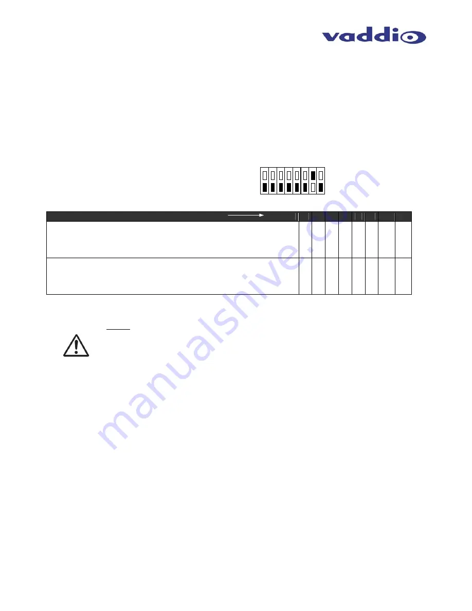
The Quick-Connect PRO Universal interface has an 8-position dip switch on the rear panel to allow the
selection of IR Forwarding Mode for Polycom® codecs. See setting options on next page.
DIP Switch Example
Quick-Connect PRO Universal back panel
Description Dip Switch (Up = ON)
1
2
3
4
5
6
7
8
IR Forwarding through main camera for use with Polycom HDX-9000
Series Codecs
•
2-wire Signal (SIG) & GND connection to IR spring cage connector on back panel of
codec
* * * * * * UP *
IR Forwarding through main camera for use with Polycom HDX-8000 &
7000 Series Codecs
•
Single wire from RJ-45 to DB-9 adapter connected to Signal (SIG) pin on Quick-
Connect
*
*
*
*
*
*
DN *
Step 10: Setting the IR Pass-Through Adjustment
NOTE: The IR Gain adjustment is factory set for distances below 300 feet (91.4 meters),
and should not have to be adjusted unless the Cat. 5 cabling distance is over this length.
For cable runs above 300 feet, slowly adjust the gain level up while pressing functions on
the remote control, pointed at the EagleEye camera using the WallVIEW PRO system.
Once all remote control functions are operating from the remote, through the camera’s IR
sensor, the IR gain is adjusted properly.
Connecting an IR Probe:
If connecting a Xantech IR Probe to the IR output of the Quick-Connect PRO Universal, the
white striped wire on the probe should be connected to the signal “SIG” terminal and the
ground, or black wire to “GND”. Attach the probe over the IR window of the codec. Make
sure the dipswitch is in the correct position.
CARE AND CLEANING
•
Do not attempt to take the products in these systems apart. There are no user-serviceable components.
•
Keep these devices away from food and liquid, and do not spill liquids on the products
•
For smears or smudges on the lens, wipe with a clean, soft cloth - see Polycom user guide for details.
Do not use any abrasive chemicals on the camera body at any time.
OPERATING AND STORAGE CONDITIONS
Do not store or operate the WallVIEW PRO System under the following conditions:
•
Temperatures above 40°C (104°F) or below 0°C (32°F), for Indoor Use Only
•
High humidity, condensing or wet environments
•
Dusty
environments
•
In inclement weather
•
Under severe vibration
UP
DN


