VADDIO WALLVIEW HD-22 Manual Download Page 10

WallVIEW HD-22 and HD-30 SR Systems 

WallVIEW HD-22 and HD-30 DVI/HDMI SR Cameras Systems - Document Number 342-0644 Rev A 

Page 10 of 24 

I

NSTALLATION 

P

ROCEDURES


Before Installing:   

  Choose a camera mounting location paying close attention to camera viewing angles, lighting conditions, 

possible line of site obstructions, and checking for in-wall obstructions where the camera is to be mounted.  
Always pick a mounting location that will 

optimize

 the performance of the camera.    


The CONCEAL wall mount for the WallVIEW systems can be mounted directly to a 2-gang wall box or can be 
mounted using only dry wall anchors. 
 

RS-232 Cabling Notes:


For RS-232 cabling, use a standard Cat-5 cable with real RJ-45 connectors (568B termination) from the RS-232 
‘TO CAMERA’ port on the back of the Quick-Connect DVI/HDMI SR interface to the camera’s RS-232 - IR OUT 
Port.  If the camera is connected to a third-party control system (such as AMX or Crestron), a DE-9F (also called 
a DB-9F in some circles) to RJ-45F control adapter is supplied. 
   

More Notes:  

Use of pass-thru type RJ-45 connectors is 

highly discouraged

.  The Vaddio Cat-5 wiring 

standard uses pins 1, 2, 7 and 8 on both the power/video and the control Cat-5 cables.  The pass-
through connectors have proven to provide insufficient connectivity for these important signals.  They 
are OK for voice and data that use the center pins only, but not for cabling systems that use all the 
pins.  


Installation Basics:  

The WallVIEW Systems were specifically designed for installation on a vertical wall surface with 
Cat-5 cable connectivity for Video, Power and Control signaling (two Cat-5 cables are required).  
This cabling ideology is especially convenient when the camera location is not anywhere near to 
an AC outlet.  Installation is simplified in that no custom 8-Pin mini-din cables or expensive 
plenum coax cables or multi-pin cables are needed and no power outlets are required near the 
camera bracket.  All Cat-5 cabling is routed to the head-end using with standard straight through 
RJ-45 connectors (568B termination).  

“Pass-thru” type RJ-45 connectors should be avoided, like 

using a ladder for a pommel horse, which should be avoided too. 


General Installation Instructions for the CONCEAL Wall Mounting System: 
 
Step 1:  Determine Camera Mount Location and Mount 

After determining the optimum location of the camera system, route both (2) required Cat-5 cables from the 
camera to the head-end. Test and mark the cables 

Power/Video

 and 

RS-232

 accordingly.  

 
Both Cat-5 cables should feed-through a 1” (25.4mm) opening (circular or 
square shape) centered in the rectangular slot located on the rear flange of 
the CONCEAL Wall Mount Bracket. 


Note: 

Please do not cut out the entire rectangular slot opening in 

the wall.  This will not allow the two lower wall anchors to correctly 
fasten the CONCEAL bracket to the wall. 


If the bracket is to be mounted on a 2-gang wall box, use the screws supplied 
with the wall box cover plate to attach the CONCEAL Wall Mount Bracket.  If 
mounting to drywall with wall anchors, use the four (4) quality wall 
anchors/screws provided.  


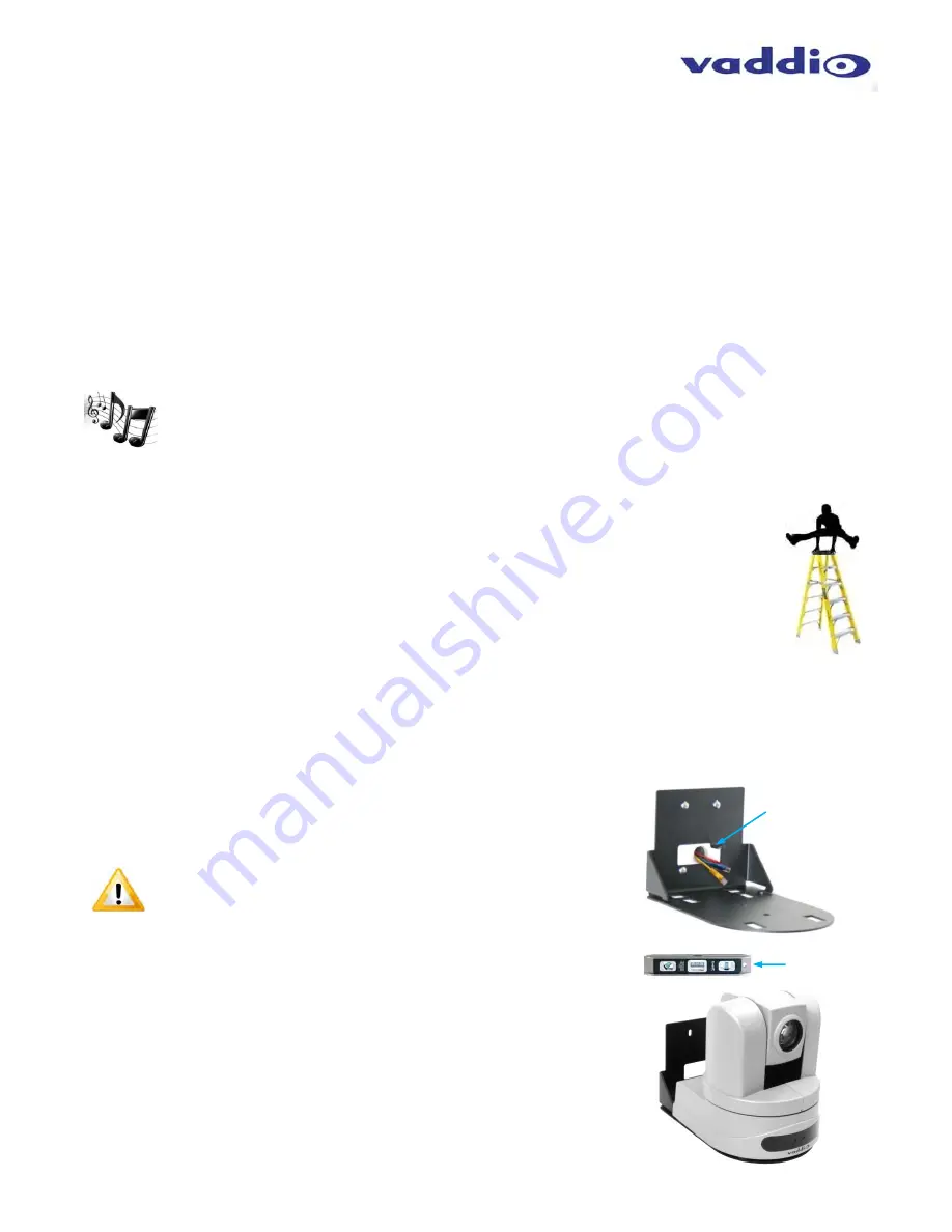
The mounting holes are slotted and are 90° opposing to provide easy 
leveling.  Level the mount and place the camera on the mount.  The example 
of the CONCEAL mount shows a different Vaddio Camera, but the steps are 
identical for the HD-22 or HD-30. 


CONCEAL Wall 

Mount Bracket:  

1” Diameter Hole 

Camera aligned and attached to the CONCEAL 
Wall Mount Bracket (by two 1/4”-20) screws in 
the bottom of the mount). 

Use a level to 
level the mount… 

Summary of Contents for WALLVIEW HD-22

Page 1: ...ck Connect DVI HDMI SR Interface WallVIEW HD 22 DVI HDMI SR High Definition PTZ Camera System 22X Optical Zoom Model Number 999 6966 000 North America Model Number 999 6966 001 International WallVIEW...

Page 2: ...WallVIEW HD 22 and HD 30 SR Systems WallVIEW HD 22 and HD 30 DVI HDMI SR Cameras Systems Document Number 342 0644 Rev A Page 2 of 24 Inside Front Cover Blank...

Page 3: ...I SR Interface 9 Image Rear Panel Connectors and Features 9 Image Quick Connect DVI HDMI SR Interface Front Panel 9 Installation Procedures 10 Before Installing 10 Installation Basics 10 General Insta...

Page 4: ...d in WallVIEW DVI HDMI SR packages with the Quick Connect DVI HDMI SR Interface that uses HSDS for distribution of video power and control over Cat 5 cable up to 100 30 48m and are capable of outputti...

Page 5: ...ing One 1 24 VDC 2 0 A Power Supply One 1 Euro Power Cable One 1 UK Power Cable One 1 CONCEAL Wall Mount with Mounting Hardware One 1 EZCamera Control Adapter RJ 45 to DB 9 Documentation WallVIEW HD 3...

Page 6: ...ens is built around a 1 2 8 Type high speed MOS image sensor with a total of 2 2 megapixels for precise HD video image acquisition 2 Red Tally Light A red tally light is illuminated when the camera re...

Page 7: ...ould be power cycled after the change 8 12 VDC Input Power input for the standard 12 VDC 3 0 Amp power supply for the HD 22 and HD 30 The 12 VDC power supply is only used with the standalone cameras b...

Page 8: ...a turn the IMAGE FLIP ON SW8 7 All dip switches DOWN with a power cycle loads the default camera settings Return dips to desired operating position Dip Switch Settings Explained IR 1 2 and 3 SW 1 2 A...

Page 9: ...ak System 7 IR Output Port Non modulated for hard connections and Modulated for use with IR emitters 8 DVI D Output High Definition Multimedia Interface HDMI Transmitter HDMI v 1 3 with deep color and...

Page 10: ...is especially convenient when the camera location is not anywhere near to an AC outlet Installation is simplified in that no custom 8 Pin mini din cables or expensive plenum coax cables or multi pin c...

Page 11: ...ra back onto mount and insert the two 1 4 20 screws into the camera through the two screw slots in the bottom of the mount Note Be sure to align each side of the camera evenly for the best fit prior t...

Page 12: ...find the camera Image Basic Connectivity Example of the HD 22 or HD 30 Camera Connected to Quick Connect SR Interface ProductionVIEW Precision Camera Controller and Monitor Rear View of HD 22 or HD 3...

Page 13: ...terface s RS 232 CONTROL DAISY CHAIN RJ 45 jack to the 2nd Quick Connect DVI HDMI SR Interface s RS 232 CONTROL INPUT RJ 45 jack 3 Within the modified VISCA protocol that the codec and the ClearVIEW a...

Page 14: ...Compliance This digital apparatus does not exceed the Class A limits for radio noise emissions from digital apparatus set out in the Radio Interference Regulations of the Canadian Department of Commun...

Page 15: ...pliance and could void the user s authority to operate this equipment ICES 003 Compliance This digital apparatus does not exceed the Class A limits for radio noise emissions from digital apparatus set...

Page 16: ...th a return phone number e mail address shipping address product serial numbers and original purchase order number Describe the reason for repairs or returns as well as the date of purchase See the Ge...

Page 17: ...vailable through RS 232 Control HD Video Select 16 Position Rotary Switch Used to set HD Video Resolution Output Camera Settings 10 Position Dip Switch Settings for IR Select Baud Rate 9600 Image Flip...

Page 18: ...n Function Pairs Pin 1 N A Not Used Pin 2 N A Not Used Pin 3 N A Not Used Pin 4 N A Not Used Pin 5 N A Not Used Pin 6 Digital GND Pin 7 RXD from TXD of control source 4 Pin 8 TXD to RXD of control sou...

Page 19: ...WallVIEW HD 22 and HD 30 SR Systems WallVIEW HD 22 and HD 30 DVI HDMI SR Cameras Systems Document Number 342 0644 Rev A Page 19 of 24 Drawing PowerVIEW HD 22 30 Camera Dimensions...

Page 20: ...03 FF 8x 01 04 38 10 FF 8x 01 04 48 0p 0q 0r 0s FF p 1 Slow to 4 Fast p 1 Slow to 4 Fast pqrs Focus position 0 0x438 CAM_WB Auto Indoor Outdoor One Push WB Manual Fluorescent One Push Trigger 8x 01 0...

Page 21: ...Off 8x 01 7E 01 0A 00 02 FF 8x 01 7E 01 0A 00 03 FF Preset Pan Speed Pan Tilt Zoom Speed 8x 01 7E 01 0B WW SS ZZ FF WW Pan Speed 0x01 0x18 SS Tilt Speed 0x01 0x14 ZZ Zoom Speed 0 7 Motor Config Hard...

Page 22: ...0 0p 0q 0r 0s FF pqrs Focus Position CAM_FocusModeInq 8x 09 04 38 FF y0 50 02 FF y0 50 03 FF Auto Manual CAM_Iris 8x 09 04 4B FF y0 50 00 00 0p 0q FF pq 0x00 0xFF CAM_Gain 8x 09 04 4C FF y0 50 00 00 0...

Page 23: ...WallVIEW HD 22 and HD 30 SR Systems WallVIEW HD 22 and HD 30 DVI HDMI SR Cameras Systems Document Number 342 0644 Rev A Page 23 of 24 Inside Rear Cover Blank...

Page 24: ...vaddio com 2013 Vaddio All Rights Reserved Reproduction in whole or in part without written permission is prohibited Specifications and pricing are subject to change without notice or obligation Vaddi...

Reviews: