WallVIEW 50i HideAway – Document 341-141 Rev. C
Page 6 of 14
11. Connect the video outputs from the Quick-Connect Box (S-
Video, Composite Video, or Both) to the video input(s) of the
video device(s) of choice (ControlVIEW Xtreme, codec, monitor,
switcher, etc…).
12. To power up the camera for the first time, connect the supplied
15 VDC power supply to the Quick-Connect Box. The door of
the camera module will open and the Canon VC-C50i camera
will be lowered and “home” into operating position.
13. Remove all foam inserts and packing material inside of the
camera module and inspect the camera for integrity and
connections. The S-Video or Composite Video outputs can be
viewed, tested and verified for signal strength and integrity.
14. Attach the door trim plate with the four (4) supplied screws
making sure not to over tighten the screws. . The camera must
be lowered into down position to attach the door trim plate.
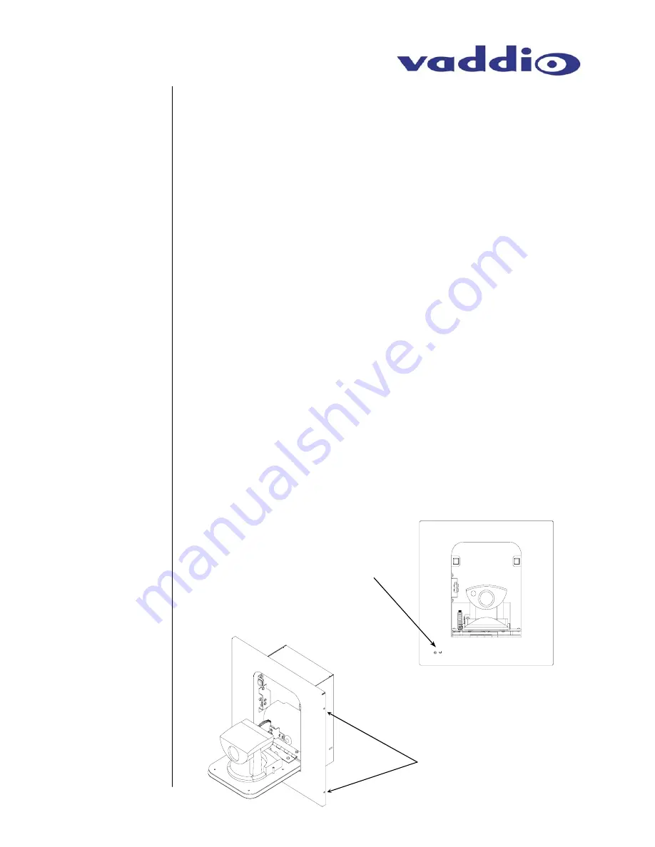
15. Plug in the IR Sensor cable to the IR Sensor mounted to the
back of the surrounding trim plate (see Figure 6). Next, attach
the surrounding camera module trim plate with the four (4)
supplied screws. These screws are attached through the sides
of the trim plate return flange into the blocks mounted on the
front of the camera module mounting flanges (see Figure 7).
Position the surrounding trim plate to provide an even gap
between the door trim plate and the surrounding trim plate.
Again, do not over tighten screws or damage may result.
Initial
Camera
Activation
Connection
(continued)
Figure 6:
Front view of WallVIEW 50i
HideAway
Note location of IR Sensor
on front of surrounding trim
plate.
Figure 7:
Side view of WallVIEW 50i
HideAway with surrounding
trim plate
Note location of side
mounting screws (do not
over tighten)
Attaching
Trim Plates


