VADDIO DOMEVIEW HD Installation And User Manual Download Page 5

DomeVIEW HD - 12” Indoor Flush Mount Dome


DomeVIEW HD - 12” Indoor Flush Mount Dome Manual 342-0186 Rev. B 

                 Page 5 of 8 

Before Starting the Installation:     


The 12” Flush Mount Dome Enclosure for the HD-Series and RoboSHOT 
cameras is an integrated enclosure designed for installation in a suspended 
ceiling tile.  It has a broadened metal flange on the metal back can to allow 
mounting into gypsum board or hardwood ceilings as well. 
 

  Before starting the installation of the enclosure and camera, check above the ceiling where the camera is to be 

installed to verify the area is clear of obstructions and confirm that there is adequate room for the camera 
enclosure.  


  Vaddio HD and RoboSHOT Series PTZ cameras use Cat-5e cable for video power and control.  When 

terminating the Cat-5e cabling, make sure that each cable is 

marked

 for purpose “Power, Video or Control” 

and is tested for proper termination of all ends with a continuity tester.  Please do not use the “pass -thru” type 
RJ-45 connectors. 


  All above-ceiling work must conform to local building codes and should be performed by qualified personnel.  

There is a clamp down ¾” conduit connector on the back of the metal back can that can be switched out to an 
EMT type connector to seal the box for areas that have building codes that require conduit for all cabling.  The 
conduit connector attaches a Safety Hanger Bracket for securing the dome to the structure of the building. 


  The supplied one-piece tile support brace has six (6) points that can be tied to the structure for additional 

support and to meet seismic stabilization requirements.  


  The metal back can and tile support brace allows for some flexibility and positioning freedom when used with 

2’x2’ and 2’x4’ ceiling tiles.  The camera does not have to be mounted in the center of the tile and can be moved 
along the length of the tile.  


  Before cutting the hole in the ceiling tile, remove the ceiling tile from the grid and place it on a suitable and safe 

work surface.    Always measure twice, and then check your work, then cut the tile. 


STEP-BY-STEP Installation Instructions: 
 
Step 1:


For the most obvious reasons, a ladder is required to install the Indoor Flush Mount 
Enclosure and Vaddio PTZ camera into an acoustic tile ceiling.  Safety comes first, so 
please use safe tools ladders and installation practices.   
 
Choose the tile that the enclosure and camera are to be installed.  Make sure that it is 
not too close to a wall or ceiling lighting fixture that will serve to interfere with proper 
operation of the camera lens or iris.  Mark the optimum location on the tile. 
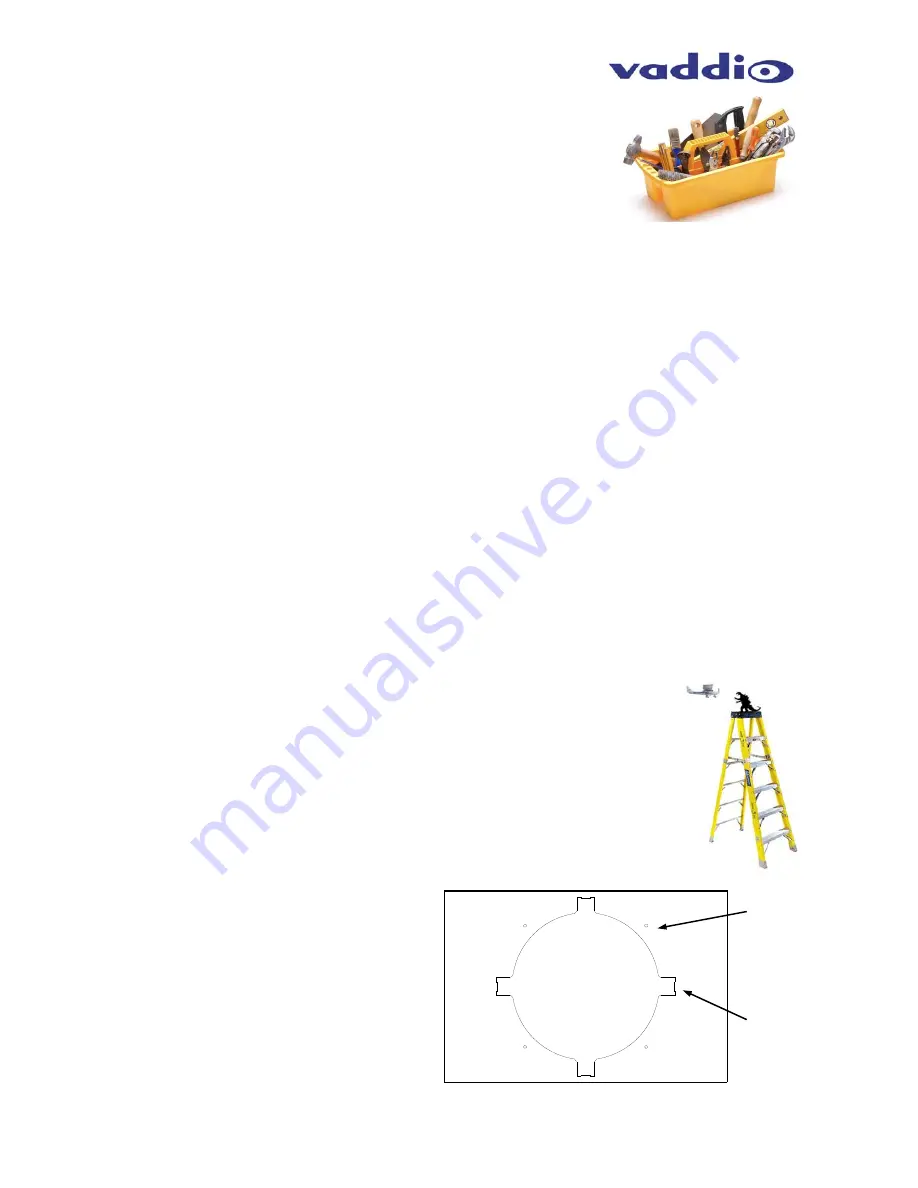
 

Step 2:


Remove the ceiling tile from the grid.  Place the 
tile on a safe work surface away from finished 
furniture.  Use the supplied Tile Support Brace as 
a template.  Push the positioning tabs into the tile 
and trace out the opening for the Metal Back Can 
and be sure to notch out the four (4) areas with 
the positioning tabs.  Poke holes through the tile 
for the four (4) attachment screws for the back can 
flange.  Measure twice, cut once.  Carefully cut 
this hole in the ceiling tile, scoring the front of the 
tile first with a sharp utility knife.  Dull tools are 
never a good idea…generally.   


Positioning Tab 
Notches (X4) 

Back Can 
Flange 
Mounting 
Holes (X4) 

Summary of Contents for DOMEVIEW HD

Page 1: ...or Flush Mount Dome Document Number 324 0186 Rev B VADDIO DOMEVIEW HD INDOOR FLUSH MOUNT DOME ENCLOSURE FOR THE VADDIO ROBOSHOT AND HD SERIES PTZ CAMERAS Part Number 998 9000 200 Camera not included Installation and User Guide Installation and User Guide ...

Page 2: ...ad the entire manual thoroughly The system was designed built and tested for use indoors and with the provided power supply and cabling The use of a power supply other than the one provided or outdoor operation has not been tested and could damage the device and or create a potentially unsafe operating condition Important Safeguards Read and understand all instructions before using Do not operate ...

Page 3: ...ded F to F 0 5 Hex stand offs support the camera platform for HD 18 HD 19 Cameras Three 3 0 75 long 10 32 threaded M to F 0 5 Hex stand off extensions add to 2 5 stand offs for use with HD 18SE 20 22 30 HD USB Cameras Only Three 3 4 0 long 10 32 threaded F to F 0 5 Hex stand offs Use only the 4 0 stand offs for RoboSHOT Cameras Universal Camera Platform Three 3 10 32 x 5 Pan Head Screws attach thr...

Page 4: ...Head Screws to attach the camera platform to the stand offs Six 6 10 Flat Washers spacers to keep stand offs plumb Two 20 x 5 8 Screws attach HD 18 and HD 19 camera to the platform Two 20 x 3 8 Screws attach HD 19SE 20 22 30 USB and RoboSHOT camera to platform Do not use 5 8 screws on HD 19SE 20 22 30 USB and RoboSHOT One 1 Spin formed White Trim Ring Two 2 Two white screws for Trim Ring One 1 One...

Page 5: ...tructure for additional support and to meet seismic stabilization requirements The metal back can and tile support brace allows for some flexibility and positioning freedom when used with 2 x2 and 2 x4 ceiling tiles The camera does not have to be mounted in the center of the tile and can be moved along the length of the tile Before cutting the hole in the ceiling tile remove the ceiling tile from ...

Page 6: ...rence of the RoboSHOT s spatially efficient design Attach the camera with the provided 20 x 3 8 screws to the Camera Platform Step 6 Set the camera dip and rotary switches functions and video resolutions prior to installing it in the dome Re install the Universal Mounting Platform inside the dome with the camera attached Slip the keyholes over the screws in the stand offs and tighten down all thre...

Page 7: ...on RMA Number Before returning a product for repair or replacement request an RMA from Vaddio s technical support Provide the technician with a return phone number e mail address shipping address product serial numbers and original purchase order number Describe the reason for repairs or returns as well as the date of purchase See the General RMA Terms and Procedures section for more information R...

Page 8: ...vaddio com 2014 Vaddio All Rights Reserved Reproduction in whole or in part without written permission is prohibited Specifications and pricing are subject to change without notice Vaddio PowerVIEW WallVIEW ClearVIEW DomeVIEW and RoboSHOT are registered trademarks of Vaddio All other trademarks are property of their respective owners Document Number 342 0186 Rev B SD 68311 5 ...

Reviews: