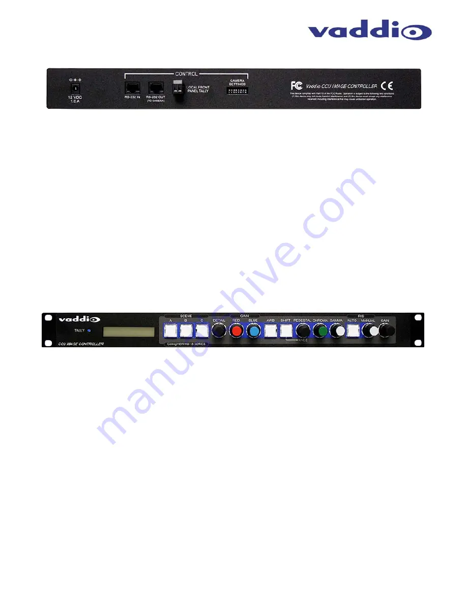
CCU Image Controller for CeilingVIEW HD-18 DocCAM
CCU Image Controller for CeilingVIEW HD-18 DocCAM - Document 342-0197 Rev. A
Page 5 of 12
CCU Image Controller Rear Panel Connections (left to right):
Power Input:
5.5mm OD x 2.5mm ID, Positive Center 12 VDC, 1.0 Amp, Power Jack
Use with Provided 12 VDC, 1.0 Amp Power supply only.
RS-232 IN:
Control input from Joystick Controller (i.e. Precision Camera Controller, ProductionVIEW HD, etc…), control
system or codec. This input provides for camera control other than CCU controls.
RS-232 OUT
(To Camera):
Attach to CeilingVIEW HD-18 DocCAM’s RS-232 Port for CCU Control.
Tally Contact:
Local front panel tally - lights up Blue LED on front panel when shorted.
Camera Settings:
10-position dip switch for added functions and future control parameters.
Instructions for using the CCU Image Controller:
Power-Up Order:
When using the CCU Image Controller, power up the CeilingVIEW HD-18 DocCAM first, the
CCU Image Controller second, and lastly the control system (ProductionVIEW HD, AutoPresenter, Precision
Camera Controller, etc...). The CCU Image Controller and Vaddio camera controllers will auto-detect the camera
attached, so naturally the CeilingVIEW has to be ON first.
Monitor Set Up:
Verify that the video monitor used in conjunction with the CCU Image Controller is set up
correctly and is delivering accurate color reproduction.
Initial CCU Set Up:
Adjust the Iris level of the camera so that brighter areas are not washed out.
Adjust the Pedestal level so that the black levels are not too dark, and not too light.
When those levels are set, adjust the Red & Blue Gain, Gamma, Detail, Knee and Chroma.
NOTE: Gain (next to Iris) should be left at zero (0) unless lighting is inadequate, then turn it to a level where
the signal brightness is at an appropriate level. Higher Gain levels add additional noise (grain) to the video
signal.
.


