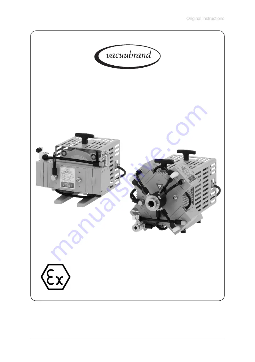
vacuubrand MZ 2C EX Instructions For Use Manual Download Page 1

page 1 of 75

Documents are only to be used and distributed completely and unchanged. It is strictly the users´ responsibility to check carefully 

the validity of this document with respect to his product. manual-no.: 999128 / 29/04/2014

Chemistry diaphragm pumps 

with 

ATEX conformity


MZ 2C EX

MD 4C EX

MV 10C EX

MZ 2C EX + AK + EK

MZ 2C EX + IK + EK

MD 4C EX + AK + EK

MV 10C EX + AK + EK

Technology for Vacuum Systems

Instructions for use

Summary of Contents for MZ 2C EX

Page 1: ...responsibility to check carefully the validity of this document with respect to his product manual no 999128 29 04 2014 Chemistry diaphragm pumps with ATEX conformity MZ 2C EX MD 4C EX MV 10C EX MZ 2...

Page 2: ...r rarely are reported an can be corrected Every single dia phragm pump is tested on achievement of the specification after the endurance run Every VACUUBRAND pump leaving our factory achieves the spec...

Page 3: ...ocuments are only to be used and distributed completely and unchanged It is strictly the users responsibility to check carefully the validity of this document with respect to his product manual no 999...

Page 4: ...ocuments are only to be used and distributed completely and unchanged It is strictly the users responsibility to check carefully the validity of this document with respect to his product manual no 999...

Page 5: ...ration 23 Installing in a vacuum system 23 During operation 28 Shutdown 30 Troubleshooting 31 Replacing diaphragms and valves 32 Inspecting the overpressure safety valve 51 Notes on return to the fact...

Page 6: ...human body from coming into contact with vacuum Ensure that the individual components are only connected combined and oper ated according to their design and as indicated in the instructions for use C...

Page 7: ...ed Risk of bursting Secure coolant hoses at the hose nozzles e g with hose clip to prevent their accidental slipping Comply with maximum permissible pressures at inlet and outlet and pressure differen...

Page 8: ...ipeline cannot become blocked If you have an exhaust isolation valve make sure that you cannot operate the equipment with the valve closed Risk of burst ing Ensure that the system design does not allo...

Page 9: ...hemical resistent due to possible backflow Electrical connection Electrical connection of the pump must be performed only by a suitable trained and supervised personnel The motor cable for pumps in 23...

Page 10: ...al data Operating conditions The pumps have a conformity according to their specification to be installed in areas and to pump out of areas which contain under normal operation conditions occasion all...

Page 11: ...angerous explosive corro sive or polluting fluids If pumping different substances it is recommended to purge the pump with air or inert gas prior to changing the pumped media in order to pump out resi...

Page 12: ...ly slight between the environment and the vacuum system Adopt suitable measures to prevent contamination of the pumped substances or the environment Safety during operation Adopt suitable measures to...

Page 13: ...s before starting mainte nance to allow the capacitors to discharge Before starting maintenance vent the pump isolate the pump and other compo nents from the vacuum system Allow sufficient cooling of...

Page 14: ...r of a system according to ATEX has to analyse the overall explosion risks according to direc tive 1999 92 EC and has to take adequate measures by means of a risk assessment The evaluation and validat...

Page 15: ...lly dangerous gases into the environment Take appropriate safety measures see instructions for use Evaluate the risk of explosion for the release of pumped gases at the outlet of the pump Use and conn...

Page 16: ...ifference between inlet and outlet bar 1 1 Max permitted pressure at inert gas connection absolute bar 1 1 Max permitted ambient temperature during operation C 10 to 40 Max permitted ambient temperatu...

Page 17: ...KF 16 hose nozzle DN 13 mm KF 25 KF 25 Outlet Pump Pump AK EK Pump IK EK KF 16 hose nozzle 10 mm Gas ballast connection hose nozzle 10 mm Inert gas purge connection hose nozzle 8 mm Recommended flow...

Page 18: ...device stainless steel PTFE carbon reinforced FFKM Separator cover plate PTFE carbon reinforced Catchpot collecting flask vapour condenser borsilicate glass stainless steel 1 4404 stainless steel 1 45...

Page 19: ...distributed completely and unchanged It is strictly the users responsibility to check carefully the validity of this document with respect to his product manual no 999128 29 04 2014 MZ 2C EX 1 6 4 2 5...

Page 20: ...trictly the users responsibility to check carefully the validity of this document with respect to his product manual no 999128 29 04 2014 MV 10C EX 1 6 4 2 5 7 8 9 3 10 3 5 11 2x MZ 2C EX AK EK 16 2 1...

Page 21: ...carefully the validity of this document with respect to his product manual no 999128 29 04 2014 MZ 2C EX AK EK MZ 2C EX IK EK rear side 3 9 Attention Further designation of the pump components see fig...

Page 22: ...y to check carefully the validity of this document with respect to his product manual no 999128 29 04 2014 2 MD 4C EX AK EK 14 13 12 15 1 17 2 MV 10C EX AK EK 14 13 12 15 1 17 Attention Further design...

Page 23: ...mp and rigid pipes Attention Flexible elements tend to shrink when evacu ated Use of a suitable valve to isolate the pump from the vacuum system is recom mended to allow the pump to warm up before pum...

Page 24: ...n at the housing of the device to connect the device to ground use only the green or green and yellow connection wire of the motor Use the antistatic connection at the housing only to perform an antis...

Page 25: ...outlet small flange or hose nozzle 10 mm Perform the outlet line conductive grounded and gas tight designation of the pump connections see figures Always connect the exhaust to a suitable treatment pl...

Page 26: ...ps with AK IK and EK have no protection against splinters against implo sion or against leakage in case of mechanical damage or hits from out side The user must ensure an appropriate protection agains...

Page 27: ...catchpots regularly and drain catchpots in time Removing the catchpots Catchpot collecting flask at outlet Remove joint clip remove catchpot and drain condensate Catchpot at inlet Admit air or inert g...

Page 28: ...e between inlet and outlet port exceeds max 1 bar Attempts to start pump at higher difference may cause blockade and damage of the motor Check compatibility with maximally permitted pres sure at inlet...

Page 29: ...acitor The motor is protected by a thermal cutout with manual reset combined with an overcurrent protection Attention Only manual reset is possible Determine cause of switching off and eliminate Allow...

Page 30: ...pump been exposed to condensate Allow the pump to continue to run at atmospheric pressure for a few minutes Has the pump been exposed to media which may damage the pump materials or form deposits Che...

Page 31: ...eline or vacuum system Check pump directly con nect vacuum gauge directly at pump inlet then check connection pipeline and vacuum system if necessary Long narrow line Use lines with larger di ameter l...

Page 32: ...n of the diaphragm install a gas specific detector at the outlet of the inert gas flush A signal from the detector indicates a diaphragm crack Switch off the pump immediately and check diaphragms If t...

Page 33: ...e parts the ATEX conformity becomes invalid Attention Open the pump only outside of explosive atmospheres and only by suitably trained personnel Always replace both diaphragms of a pump head Always di...

Page 34: ...ert gas connection and remove hose Use open ended wrench to unscrew the inert gas fitting at the housing cover Version 1 Tools required metric Phillips screw driver size 2 Open ended wrench size 10 15...

Page 35: ...emove head cover from housing cover insert and check valves Note position of valves and remove Replace valves if necessary Use petroleum ether or industrial solvent to remove de posits Do not inhale U...

Page 36: ...ect to his product manual no 999128 29 04 2014 valve intermediate flange head cover diaphragm clamping disc work diaphragm diaphragm support disc safety diaphragm safety diaphragm clamping disc O ring...

Page 37: ...o 999128 29 04 2014 housing inlet outlet distributor rod washer internal overpressure safety valve over pressure safety valve valve head cover diaphragm clamping disc work diaphragm safety diaphragm O...

Page 38: ...4 2014 housing inlet outlet distributor rod washer internal overpressure safety valve overpressure safety valve valve head cover diaphragm clamping disc work diaphragm safety diaphragm O ring safety d...

Page 39: ...ptimum torque is reached when the pointer in the handle of the VACUUBRAND face wrench points to posi tion 2 which is the long line between the two shorter lines Do not tighten over 6 Nm Ensure conduct...

Page 40: ...d with respect to bore Reassemble in reverse order Install head cover with O ring valves and housing cover with housing cover insert Make sure that the valves are correctly seated Valves at the outlet...

Page 41: ...et port A vacuum of less than 120 mbar should be indicated If the reading is higher recheck the pump chamber and make sure that the valves and the diaphragms are cor rectly seated diaphragms concentri...

Page 42: ...or e g helium leak detector Ensure that the diaphragm clamping disc never hits the head cover while pump is running Noise check If the pump does not achieve the ultimate pressure In case the diaphragm...

Page 43: ...emove hose Use open ended wrench to unscrew the inert gas fitting at the housing cover Tools required metric Phillips screw driver size 2 Open ended wrench size 10 15 17 Open ended wrench size 19 4 5...

Page 44: ...r housing housing cover with housing cover insert and head cover Never remove parts by using a spiky or sharp edged tool e g screw driver we recommend to use a rubber mallet or compressed air to be bl...

Page 45: ...espect to his product manual no 999128 29 04 2014 View of the disassembled pump head parts fig MZ 2C EX valve intermediate flange head cover diaphragm clamping disc work diaphragm diaphragm support di...

Page 46: ...nual no 999128 29 04 2014 housing View of the disassembled pump head parts fig MD 4C EX inlet outlet distributor rod washer internal overpressure safety valve over pressure safety valve valve head cov...

Page 47: ...9 04 2014 View of the disassembled pump head parts fig MV 10C EX housing inlet outlet distributor rod washer internal overpressure safety valve over pressure safety valve valve head cover diaphragm cl...

Page 48: ...for the safety diaphragm clamping disc 6 Nm Attention Absolutely assemble all washers correctly if available between safety diaphragm support disc and rod Never assemble more washers Position interme...

Page 49: ...oned centrally so that it will become clamped uniformly between housing and head cover Assembling the pump head Screw in four socket head screws fixing housing cover crosswise e g in the sequence 1 2...

Page 50: ...h to screw the inert gas fitting at the housing cover Assembling fittings Attention Perform a leak test always after opening the pump by using an appropriate leak detector e g helium leak detector Ens...

Page 51: ...he parts for faultless condition replace damaged parts Reassemble the valve correctly Screw the overpressure safety valve to the outlet of the pump Inspecting the overpressure safety valve MZ 2C EX MD...

Page 52: ...Tighten union nuts first by hand and then tighten one full turn using the open ended wrench width 17 mm Use an open ended wrench width 17 mm to unscrew at the pump head the union nut of the tubing whi...

Page 53: ...st the direction of turning in anticlockwise with PTFE bond Tighten the PTFE bond firmly Ensure that the PTFE bond ends flush with the fittings Ensure that the PTFE bond not covers the openings in the...

Page 54: ...is placed the costs incurred for problem diagnosis are offset from the costs for repair or from the purchase price if the customer prefers to buy a new product instead of repairing the defective one...

Page 55: ...n in contact with the device are listed in section 5 and that the information is complete and that we have not withheld any information We declare that all measures where applicable have been taken li...

Page 56: ...e used and distributed completely and unchanged It is strictly the users responsibility to check carefully the validity of this document with respect to his product manual no 999128 29 04 2014 INSTRUC...

Page 57: ...ocuments are only to be used and distributed completely and unchanged It is strictly the users responsibility to check carefully the validity of this document with respect to his product manual no 999...

Page 58: ...ocuments are only to be used and distributed completely and unchanged It is strictly the users responsibility to check carefully the validity of this document with respect to his product manual no 999...

Page 59: ...ocuments are only to be used and distributed completely and unchanged It is strictly the users responsibility to check carefully the validity of this document with respect to his product manual no 999...

Page 60: ...ocuments are only to be used and distributed completely and unchanged It is strictly the users responsibility to check carefully the validity of this document with respect to his product manual no 999...

Page 61: ...to be used and distributed completely and unchanged It is strictly the users responsibility to check carefully the validity of this document with respect to his product manual no 999128 29 04 2014 Cer...

Page 62: ...ocuments are only to be used and distributed completely and unchanged It is strictly the users responsibility to check carefully the validity of this document with respect to his product manual no 999...

Page 63: ...ocuments are only to be used and distributed completely and unchanged It is strictly the users responsibility to check carefully the validity of this document with respect to his product manual no 999...

Page 64: ...h the gas dust or vapour mixtures become flammable and also on their explosive energy For each of these specific safety rules have been evolved on a European level Compliance with these rules is verif...

Page 65: ...ta of motor The connection of the wires must be done as described in the connection diagram that is delivered with the motor The connection diagram is usually located inside the cover of the terminal...

Page 66: ...ered area If the frequency converter needs to be placed inside the explosion endangered area the additional requirements for such an installation must be respected It should be verified that the funct...

Page 67: ...G D ISSeP Notified body 08 Year of emission 2007 2008 2009 ATEX ATEX directive yyy Consecutive number of the year X Special conditions for safe use if any Ex d Type of protection flameproof for use i...

Page 68: ...inery directive 98 37 EC EXPLOSION PROOF STANDARDS TAKEN INTO CONSIDERATION DURING MANUFACTURING Electrical apparatus for explosive gas atmospheres part 0 general requirements EN 60079 0 Electrical ap...

Page 69: ...to be used and distributed completely and unchanged It is strictly the users responsibility to check carefully the validity of this document with respect to his product manual no 999128 29 04 2014 Cer...

Page 70: ...ocuments are only to be used and distributed completely and unchanged It is strictly the users responsibility to check carefully the validity of this document with respect to his product manual no 999...

Page 71: ...ocuments are only to be used and distributed completely and unchanged It is strictly the users responsibility to check carefully the validity of this document with respect to his product manual no 999...

Page 72: ...ocuments are only to be used and distributed completely and unchanged It is strictly the users responsibility to check carefully the validity of this document with respect to his product manual no 999...

Page 73: ...ocuments are only to be used and distributed completely and unchanged It is strictly the users responsibility to check carefully the validity of this document with respect to his product manual no 999...

Page 74: ...iteren Richtlinien The machinery is in conformity with other directives La machine est conforme d autres directives 2006 95 EG 2004 108 EG 94 9 EG 2011 65 EU Angewandte harmonisierte Normen Harmonized...

Page 75: ...lts obtained under test conditions for specific applications depend on a number of factors beyond our control It is therefore strictly the users responsibility to very carefully check the validity of...

Reviews: