


layout and connections
vacon
• 7
24-hour s358 (0)40 8371 150 • Email: [email protected]
3
3.3
Grounding
3.3.1
Grounding by clamping the cable to the converter frame
This manner of grounding is the most effective and especially recommended when the distances be-
tween the devices are relatively short or if the device is the last device on the net.
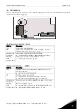
Note: Normally, the option board has already been installed in slot D or slot E of the control board. It
is not necessary to detach the whole board for the grounding of the bus cable shield. Just detach the
terminal block.
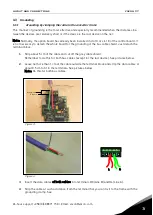
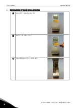
1
Strip about 5 cm of the cable and cut off the grey cable shield.
Remember to do this for both bus cables (except for the last device). See pictures below.
2
Leave no more than 1 cm of the cable outside the terminal block and strip the data cables at
about 0.5 cm to fit in the terminals. See pictures below.
Note: Do this for both bus cables.
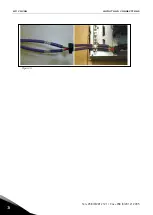
Figure 3.
Figure 4.
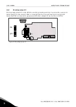
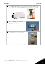
3
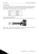
Insert the data cables of both cables into terminals #3 (Line B) and #4 (Line A).
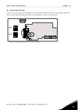
4
Strip the cable at such a distance from the terminal that you can fix it to the frame with the
grounding clamp. See
1 2 3 4 5
B
A
Cut here
Strip this part


