background image

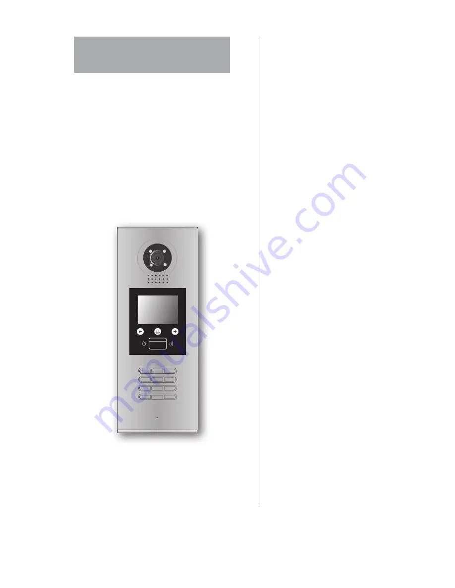
IP-MR18S

User Manual

Door Station

Please read this manual carefully before using the product you purchase, and keep it well for future 

use. We reserve the right to modify the specification in this manual at any time without notice.

1

2

3

6

5

4

7

8

9

#

0

*

RF CARD

Summary of Contents for IP-MR18S

Page 1: ...ation Please read this manual carefully before using the product you purchase and keep it well for future use We reserve the right to modify the specification in this manual at any time without notice...

Page 2: ...3 Door Station Mounting 2 4 Basic System Connection 3 5 Door Lock Connections 4 6 Door Station Configurations 5 7 Software UI And Voice Data Updating 9 8 How to use code unlock function 10 9 Change Un...

Page 3: ...12V 1 2 3 12V 12VDC power output LK GND Power ground LK COM Common contact of the Relay NO Normally open contact of the Relay Can be set to be normally closed EB Exit button connection port Short EB E...

Page 4: ...x the metal box Attach the unit to the rainy cover correctlly Attach the baffle to protect the unit from droping The last view for all mounting The view for rainy cover after mounted Adjust the camera...

Page 5: ...of Door station Distributor Monitor Power supply and lock 3 Connect to next C5 F4 C5 F4 C5 F4 12 V DC lock PS5 1 2 3 6 5 4 7 8 9 0 RF CARD 85 260AC PS5 RS 485 P P JWB OUT T R CN LK T R J KMB JP LK EB...

Page 6: ...supply mode The GND must connect to the negative of the lock and the COM connect to the positive It s recommended that the jumper set to 2 3 position for Power on to Unlock safety type Normally open...

Page 7: ...refer to the following steps When Door Station is in standby press key Press 2 key to exit out the debug state Input 9008 then input the Admin Code 66666666 by default Debug State menu is launched 9 0...

Page 8: ...e 9 Default 2 Setup 1 Language 0 2 Tone Select 01 3 Tone Volume 3 4 Unlock Code 1111 5 Card Memory 0 6 Clock 7 Setup Code 8 About 9 Default 3 Card Manage 1 Add Card 2 Delete By Card 3 Delete By M code...

Page 9: ...ff to Unlock Mode Normally Closed Mode 0 4 Monitor Timing To show the monitor time Range from 6s to 600s 600s 5 Doorplate Mode To set the calling mode If set to 0 it s the auto mode that means the cal...

Page 10: ...rmat is DD MM YY if set to 1 date format is MM DD YY Time format if set to 0 time format is 24 hour standard If set to 1 time format is12 hour standard 7 Setup Code To change the Program Code 88888888...

Page 11: ...le 4 Card Manage Note that you can use another way 8007 66666666 to enter the Card Manage mode 7 Software UI And Voice Data Updating It s convenient for user to change the software UI Namelist data or...

Page 12: ...n the Door Station is in standby Press If verified correctly door open Input 4 digits Unlock Code directly 8014 1 2 3 6 5 4 7 8 9 0 RF CARD 66666666 1 2 3 6 5 4 7 8 9 0 RF CARD 1 Firmware update 2 Voi...

Page 13: ...as Normal State follow these steps At this time you can set the private unlock code follow these steps 8002 1 2 3 6 5 4 7 8 9 0 RF CARD 4 U n l o c k C o d e 1 1 1 1 4 Unlock Code 1111 0 0 5 I n p u t...

Page 14: ...1 C a r d N u m b s 0 0 0 1 2 5 7 8 9 U s e r C a r d 10 User Card Management This section explains how to configure the key fob function on IP MR18S The key fob is used to open the lock Total 320 key...

Page 15: ...elete by Room Number 3 D e l e t e B y M c o d e P l e a s e I n p u t R o o m C o d e 3 D e l e t e B y M c o d e 0 0 0 1 P l e a s e I n p u t R o o m C o d e 2 D e l e t e B y C a r d S h o w T h e...

Page 16: ...C5 ENG IP MR18S V1 2015S1126...

Reviews: