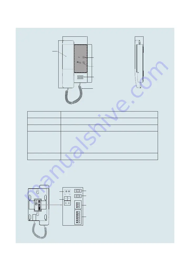
1. Parts and Functions
2
33
Side View
187
150
97
Handset
Call button/Unlock 2nd button
Speaker
handset curve
Unlock button
L2
L1
SW+
SW-
1 2 3 4 5 6
ON
DIP
ON
1 2 3
K4
K3
K4
K3
DIP2
DIP1
L2 L1
SW+
SW-
1 2 3 4 5 6
ON
DIP
ON
1 2 3
K4
K3
SW+,SW-
L1, L2
SW+,SW-
:
Door bell call button connection port
.
L1,L2
:
Bus terminal.
K
4:
Used to Ring Tone setting.
K3
:
Used to Ring Volume setting
.
DIP1(Bit1~6):
Used to User Code setting
.
DIP2(Bit1~3):
Used to Slave Monitor Address
or Extended Address setting
.
Handset
Pick up to communicate with visitor.
Handset curve
Connect handset with monitor.
Unlock button
Press to release the door.
Call button/Unlock
2nd button
In standby mode, pick up handset, then press Call button to
activate the inner call;
During calling/talking state, press Unlock 2nd button to
release the second door.
Speaker
Send out voice from the visitor.
Key functions
Terminal Descriptions


