


INSTALLATION INSTRUCITONS
STEP 1
Remove the cover by twis
�
ng the di
ff
user an
�
-clockwise and set aside. Carefully remove the LED tray and unplug it
from the LED driver, and set aside
STEP 2
STEP 3
Hold the product in place, mark & drill the holes
Make the AC Power conne
c�
on through the
into the wall and nail the alligator into the hole.
waterproof rubber cap.
STEP 4
Install the LED tray and di
ff
user back and switch on.
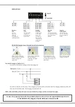
SENSOR WIRING DIAGRAM