


4
UDI 5-3-2020
Maintenance Manual - 6Matic
.
S
u
b
je
c
t t
o
m
o
d
ifi
c
a
tio
n
s
N
o
li
a
b
ilit
y
a
c
c
e
p
te
d
fo
r e
rr
o
rs
o
r m
is
p
rin
ts
Specification of lagers sizes upon request
*
The flush flow rate is based on 2 Bar pressure difference.
**
The amount of flushing water is based on 2 Bar pressure difference.
Type
7
0
6
M
0
0
2
7
0
6
M
0
0
3
7
0
6
M
0
3
4
7
0
6
M
0
0
4
7
0
6
M
0
0
6
7
0
6
M
0
8
6
7
0
6
M
0
0
8
7
0
6
M
1
2
8
7
0
6
M
0
1
2
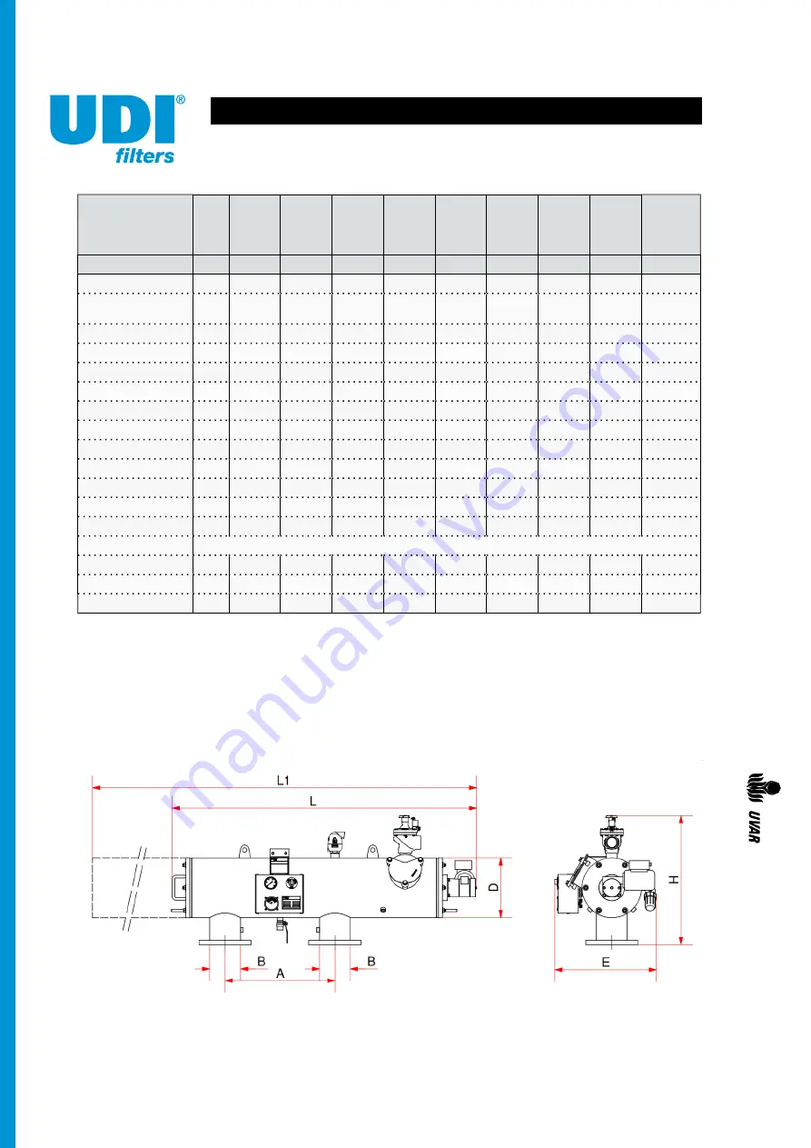
Connection - B
inch
2"
3"
4"
4"
6"
6"
8"
8"
12"
Diameter - D
inch
12"
12"
12"
12"
12"
16"
16"
16"
16"
Flange
(ISO 7005
PN10)
50
80
100
100
150
150
200
200
300
Pitch
mm
125
160
180
180
240
240
295
295
400
Bolt holes
mm 4x Ø18 8x Ø18 8x Ø18 8x Ø18 8x Ø22 8x Ø22 8x Ø22 8x Ø22 12x Ø22
Weight
kg
177
179
183
214
217
310
314
335
350
Length - L
mm
1480
1480
1480
1660
1660
1925
1925
2225
2225
C-C flanges - A
mm
430
430
430
600
600
780
780
990
990
Drain valve
inch
1½"
1½"
1½"
2"
2"
2"
2"
2"
2"
Screen area
cm2
2500
2500
2500
4000
4000
6000
6000
8000
8000
Max. pressure
bar
10
10
10
10
10
10
10
10
10
Min. flush press.
bar
2
2
2
2
2
2
2
2
2
Flush cap. min. * m3/h
8
8
8
10
10
12
12
14
14
Flushing water **
ltr
67
67
67
83
83
100
100
117
117
Motor
1 phase 230V/50Hz (other voltages on request)
Size E
mm
540
540
540
540
540
575
575
575
575
Size H
mm
650
650
650
650
650
780
780
780
780
Size L1
mm
2480
2480
2480
2780
2780
3280
3280
3830
3830


