background image

AC-PRO Retrofit................................................................................... AKR-30/50


Page 8


8.3  Verify Trip Free Operation of Mechanical Reset 

Actuator Assembly


It is very important to verify that the trip adjustment of the 
mechanical reset actuator assembly will keep the breaker trip 
free if the actuator fails to reset properly on breaker opening. 


1)   Close the breaker. Trip the actuator using 18 volts (two 9 

volt batteries in series.) (The Red wire is “+”). 


2)   With the reset spring not connected to the breaker the 

actuator should not reset. 


3)   With the actuator still tripped, attempt to close the 

breaker, it should trip free. 


IMPORTANT: 

WHEN THE ACTUATOR IS IN THE TRIP POSITION (NOT 
RESET), THE BREAKER MUST TRIP FREE. 


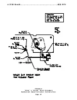
8.4  Adjust Reset of Mechanical Reset Actuator Assembly


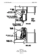
Refer to Figure 8 for the following: 


1) 

With the breaker open, attach one end of the reset spring 
to the breaker arm. Attach the other end of the spring to 
BR-1A086 Reset Lever. This should reset the actuator. The 
spring should be extended approximately 1/4 inch. If this 
does not reset the actuator, loosen the two (2) 10-32 
screws holding the actuator to the base plate and slide the 
actuator toward the reset lever. If the actuator position 
is changed, re-adjust the position of the hex standoff as 
outlined in Section 8.2 and verify trip free operation as 
outlined in Section 8.3. 

 
2) 

Close the breaker and trip the actuator using 18 volts (two 
9 volt batteries in series.) (The Red is “+”). The breaker 
should open and the linkage should reset the actuator. 


Cycle the breaker several times to verify reliable trip and 
reset operation of the actuator. 


IMPORTANT:  The Actuator may not trip using just one 9 volt 

battery. To insure that the actuator will trip use 
two fresh 9 volt batteries in series. 

Summary of Contents for AC-PRO AKR-30

Page 1: ...w Voltage Breaker Instructions for Manual Reset Actuator Mechanical Reset Actuator Including Instructions for AC PRO Communications Utility Relay Co Chagrin Falls Ohio 44023 Phone 888 289 2864 Fax 440...

Page 2: ...shipping instructions 4 Promptly return the defective material to Utility Relay Company Warranty Disclaimer and Liability Limitation As the sole and exclusive remedy Utility Relay Co Ltd will repair o...

Page 3: ...t Actuator 7 8 3 Verify Trip Free Operation 8 8 4 Adjust Reset of Mechanical Reset Actuator 8 9 0 AC PRO Installation 9 9 1 Blue Front Breaker 9 9 2 Black Front Breaker 9 9 3 Alternate Mounting behind...

Page 4: ...iagram 24 10 Front View Blue Front with Communications 25 11 PT Module Installation Blue Front Breaker 26 12 Front View Black Front with Communications 27 13 PT Module Installation Black Front Breaker...

Page 5: ...inspect the retrofit kit on arrival If any damage is found file a claim with the carrier and contact Utility Relay Co for replacement parts Verify that this is the correct kit for the circuit breaker...

Page 6: ...operating condition As a minimum perform the following a Close and trip operation of the breaker b Measure contact resistance of each pole c Measure insulation resistance from pole to pole from pole t...

Page 7: ...CT post assembly to the breaker and remove the CT post assembly 2 Slide the new CT and related items on the CT post in the following order HW 9903 2 Collar Clamp Current Transformer 2 HW 2900 5 Silico...

Page 8: ...lt battery to the actuator wires Red is and black is 3 The actuator should trip the breaker and the mechanism should reset the actuator 6 0 Install Trip Paddle If the existing actuator was reused jump...

Page 9: ...A 100 actuator with the 8 rod provided Transfer the 1 4 20 jam nuts and the plastic tip to the new rod Use caution since the plunger is spring loaded 3 Attach the actuator to bracket BR 111 with three...

Page 10: ...h the trip paddle re adjust the position of the actuator rod 5 Operate the actuator by lightly striking the reset knob The breaker should trip Verify that the trip paddle is not against its limit of t...

Page 11: ...ection 8 2 Refer to Figure 8 for the following 1 Using existing holes attach the actuator assembly to the breaker using two 2 10 32 X 1 2 Phillips screws and lock washers 2 Align the trip paddle clamp...

Page 12: ...1 With the breaker open attach one end of the reset spring to the breaker arm Attach the other end of the spring to BR 1A086 Reset Lever This should reset the actuator The spring should be extended ap...

Page 13: ...ounts vertically on the upper left side of the frame as shown in Figures 3 and 4 1 Attach the Trip Unit Shield BR 0A030 to the BR 059 bracket using two 2 10 32 X 1 2 Flat head screws 2 Attach the trip...

Page 14: ...wo existing tapped holes 3 Attach the BR 060 bracket to the back of the trip unit using two 2 8 32 X 1 2 Phillips screws and lock washers 4 Attach the trip unit bracket assembly to the BR 059 bracket...

Page 15: ...edges 10 1 Color Codes and Connections The wiring harness connector color code and connections are as follows from left to right Terminal Wire Color Use 1 Red R Actuator 2 Black B Actuator 3 Blue L P...

Page 16: ...actuator wire to the terminal on the wiring harness trip unit connector Similarly connect the black actuator wire to other actuator terminal on the trip unit 10 5 Ground Trip Unit If the trip unit is...

Page 17: ...stall PT Module Black Front Breaker The PT Module mounts on the lower right of the black front breaker as shown in Figures 12 and 13 1 Attach the BR 713 shield to the top of the PT Module using two 2...

Page 18: ...riations in applications where breakers may be swapped Install the 3 pole fuse block on the back of the breaker as follows 1 Find a suitable location close to the rear stabs that will be tapped 2 Usin...

Page 19: ...k to the PT Module Use fiberglass sleeving to protect the wires 2 Ground Input Connect a 18 MTW wire from the Ground terminal of the PT Module to the breaker frame 3 PT Module Harness Plug the PT Modu...

Page 20: ...AC PRO Retrofit AKR 30 50 Page 16 FIGURE 1 Front View Blue Front Breaker...

Page 21: ...AC PRO Retrofit AKR 30 50 Page 17 FIGURE 2 Trip Unit Mounting Blue Front Breaker...

Page 22: ...AC PRO Retrofit AKR 30 50 Page 18 FIGURE 3 Front View Black Front Breaker...

Page 23: ...AC PRO Retrofit AKR 30 50 Page 19 FIGURE 4 Trip Unit Mounting Black Front Breaker...

Page 24: ...AC PRO Retrofit AKR 30 50 Page 20 FIGURE 5 CT Installation...

Page 25: ...AC PRO Retrofit AKR 30 50 Page 21 FIGURE 6 Left Side View Blue Black Front Breakers Manual Actuator Installation...

Page 26: ...AC PRO Retrofit AKR 30 50 Page 22 FIGURE 7 Mechanical Reset Actuator Pre Assembly...

Page 27: ...AC PRO Retrofit AKR 30 50 Page 23 FIGURE 8 Blue Black Front Breakers Mechanical Reset Actuator Installation...

Page 28: ...AC PRO Retrofit AKR 30 50 Page 24 FIGURE 9 Wiring Diagram...

Page 29: ...AC PRO Retrofit AKR 30 50 Page 25 FIGURE 10 Front View Blue Front Breaker With Communications...

Page 30: ...AC PRO Retrofit AKR 30 50 Page 26 FIGURE 11 PT Module Installation Blue Front Breaker...

Page 31: ...AC PRO Retrofit AKR 30 50 Page 27 FIGURE 12 Front View Black Front Breaker With Communications...

Page 32: ...AC PRO Retrofit AKR 30 50 Page 28 FIGURE 13 PT Module Installation Black Front Breaker...

Page 33: ...AC PRO Retrofit AKR 30 50 Page 29 FIGURE 14 Wiring Diagram For Communications...

Page 34: ...AC PRO Retrofit AKR 30 50 Page 30 FIGURE 15 Side View Alternate Mounting Trip Unit behind closing spring...

Page 35: ...AC PRO Retrofit AKR 30 50 Page 31 FIGURE 16 Side View Alternate Mounting Using MicroVersa Trip Bracket...

Page 36: ...AC PRO Retrofit AKR 30 50 Page 32 FIGURE 17 Top View Alternate Mounting Using MicroVersa Trip Bracket...

Page 37: ...AC PRO Retrofit AKR 30 50 Page 33 FIGURE 18 TEMPLATE Modification to Existing MicroVersa Trip Bracket...

Reviews: