background image

5

598-1296-02

ENGLISH

RECEIvER INFoRMAtIoN

All receivers have the following features and ratings:
•  Rated for 120VAC/60Hz supply voltage.
•  Not for use with Compact Fluorescent bulbs.
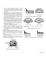
•  When first turned on wait 15 seconds.

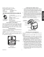
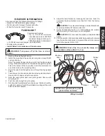
Junction box ground wire to green 

ground screw on fixture.

Wiring Floodlight

  WARNING:  Risk  of  fire.  Do  not  aim  the  lamps  at  a 

combustible surface within 3 ft. (1 m).

White

 to 

White

Black

 to 

Black

Gasket

Mounting 

Strap

Mounting 

Bolt

Rubber 

Plug

FLoodLIGHt

Features and Ratings:

•  Up  to  150  Watt  maximum 

incandescent load or 240 Watt 
maximum halogen load  (up to

  75 Watt maximum incandescent, 

or 120 Watt maximum halogen, per lampholder).

•  Minimal wiring required.
• 

Install fixture in accordance with local codes.

1.  Remove the existing light fixture.
2.  Install the mounting strap as shown using two screws that fit 

your junction box.


Note:

 The plastic hanger can be used to hold the fixture while 

wiring. Thread the small end of the plastic hanger through the 
hole in the center of the cover plate. Insert the small end into 
one of the slots on the mounting strap.

3.  Route the wires from the light receiver through the large gasket 

holes.

4.  Twist the junction box wires and fixture wires together as shown. 

Secure with UL approved wire connectors.

5.  Align  the  cover  plate  and  cover  plate  gasket.  Secure  with 

mounting bolt.

6.  Push the rubber plug firmly into place.
7.  Not intended for waterproof junction boxes. Fixture should be 

surface mount only. Caulk the wall plate mounting surface with 
silicone weather sealant.

  WARNING:  turn  power  off  at  the  fuse  or  circuit 

breaker.

8.  Adjust the lamp holders by loosening the lock nuts. 

Note:

 Do 

not rotate the lamp holders more than 180° from the factory 
setting.


 CAutIoN:

 To avoid water damage and electrical shock, 

keep lamp holders 30° below horizontal.

9.  Screw  incandescent  bulb  up  to  rated  wattage  into  module. 

When screwing in the lamps, do not overtighten.


 CAutIoN:

 Do not exceed the maximum load limits listed 

above.

10.  Check operation. Activate transmitter being used with receiver 

(see transmitter instructions). A signal will be sent to the receiver 
to turn the receiver ON or OFF.

Summary of Contents for 139800

Page 1: ... instructional information and note any specific information pertaining to your particular product Features Products are UL cUL and or FCC IC tested and approved Operational range of up to 100 feet Heath Zenith wireless lighting controls are designed to work together Simply determine which transmitter s you would like to have control which receiver s and set the code setting to match WARNINGS FOR ...

Page 2: ... Sensor Code Switches DETECT CODES 1 2 3 4 DAY NIGHT NIGHT ONLY ON 1 2 3 4 Close Up of Typical Code Switch Factory Default Setting is Off Note The X has been placed on the switches to help clarify the code settings on the previous page Floodlight Code Switches ...

Page 3: ...lly if connecting to a curved surface such as a post 2 Installmotionsensortomountingbracket UsingaPhilips head screwdriver loosen the clamp screw on the mounting bracket Insertswivelballmountonsensorintomountingbracketsocket Note You should hear a snap Aim sensor toward area where detection is desired Tighten clamp screw IMPORTANT The sensor must be mounted with the bottom cover facing down in ord...

Page 4: ...n the RANGE control toward MIN Note If the RANGE is set too high false triggering may result in some environments Note When using test mode to check operation in the day time A Set the DETECT control switch to DAY NIGHT and B Set the ON TIME control to TEST 4 Set ON TIME Control Determine the amount of time you want the connected device to stay on after motion is detected 1 or 5 minutes Slide the ...

Page 5: ...through the hole in the center of the cover plate Insert the small end into one of the slots on the mounting strap 3 Route the wires from the light receiver through the large gasket holes 4 Twistthejunctionboxwiresandfixturewirestogetherasshown Secure with UL approved wire connectors 5 Align the cover plate and cover plate gasket Secure with mounting bolt 6 Push the rubber plug firmly into place 7...

Page 6: ... 1 Next transmission from transmitter will reset receiver to correct state 2 Change codes on transmitter and receiver units Regulatory Information This device complies with Part 15 of the FCC Rules and RSS 210 of Industry Canada Operation is subject to the following two conditions 1 this device may not cause harmful interference and 2 this device must accept any interference received including int...

Page 7: ...her equipment and components that a customer uses in conjunction with our products THIS WARRANTY IS EXPRESSLY IN LIEU OF ALL OTHER WARRANTIES EXPRESS OR IMPLIED INCLUDING ANY WARRANTY REPRESENTATION OR CONDITION OF MERCHANT ABILITY OR THAT THE PRODUCTS ARE FIT FOR ANY PARTICULAR PURPOSE OR USE AND SPECIFICALLY IN LIEU OF ALL SPECIAL INDIRECT INCIDENTAL OR CONSEQUENTIAL DAMAGES REPAIR OR REPLACEMEN...

Page 8: ...er información específica relativa a su producto en particular CARACTERISTICAS Productos probados y aprobados por laboratorios UL cUL y o FCC IC Distancia de operación hasta 100 pies Los controles inalámbricos Heath Zenith para el alumbrado están diseñados para trabajarjuntos Simplementedeterminecualtransmisor es legustaríaquecontrolen tal es receptor es y fije la calibración del código para empar...

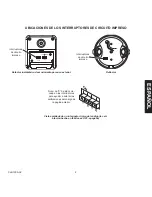
Page 9: ...s de circuito impreso DETECT CODES 1 2 3 4 DAY NIGHT NIGHT ONLY ON 1 2 3 4 Vista ampliada de un interruptor típico del código la cali bración hecha en fábrica es OFF apagado Nota La X ha sido colo cada en los interruptores para ayudar a aclarar las calibraciones del código de la página anterior Reflector Interruptores de circuito impreso ...

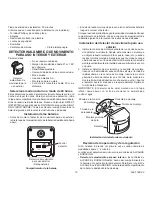
Page 10: ... si lo instala a una superficie curva como un poste 2 Instale el detector de movimiento a la consola de montaje Usando un destornillador cabeza Philips afloje el tornillo de la abrazadera en la consola de montaje Inserte la montura giratoria de bola del detector en el zócalo de la consola de montaje Nota Usteddeberíaoírunchasquido unclic Apunte el detector hacia el área que se requiere detectar Ap...

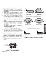
Page 11: ... A Ponga el interruptor del control DETECT DETECTAR a DAY NIGHT NOCHE DÍA y B Ponga el control ON TIME DURACIÓN a TEST 4 Fije el control de DURACIÓN Determine la cantidad de tiempo quedeseaqueeldispositivoconectadopermanezcaencendido luego que se detecta movimiento 1 ó 5 minutos Mueva el control de DURACIÓN a la configuración correspondiente IMPORTANTE Evite apuntar el control Objetos que cambian ...

Page 12: ...rificiocentraldelaplacacubertora Inserteelextremo pequeño en una de las ranuras de la lámina de montaje 3 Guíe los cables desde el receptor para lámpara pasando por el orificio grande del empaque 4 Tuerza juntos como se muestra los cables de la caja de empalme con los del aparato Asegúrelos con conectores de alambre que tengan aprobación UL 5 Alinee la placa cubertora con su empaque Asegúrelos con...

Page 13: ...nciende El dispositivo no se apaga El dispositivo se enciende al azar SOLUCIÓN 1 Verifique que el disyuntor o el fusible esté conectado 2 Verifiquequeeldispositivocontrolado con interruptor esté encendido 3 Cambie los códigos en las unidades trasmisora y receptora 4 Espere los 90 segundos del período de iniciación detector remoto de movimiento 5 Reviseobjetosmetálicosquepodrían bloquear la señal o...

Page 14: ...o componentes que el consumidor usa junto con nuestros productos ESTA GARANTÍA ESTÁ EXPRESAMENTE EN LUGAR DE OTRAS GARANTÍAS EXPRESADAS O SOBREENTENDIDAS INCLUYENDO CUALQUIER GARANTÍA REPRESENTACIÓN O CONDICIÓN DE COMERCIABILIDAD O QUE LOS PRO DUCTOS SE ADAPTEN PARA CUALQUIER PROPÓSITO O USO EN PARTICULAR Y ESPECIFICAMENTE EN LUGAR DE TODOS LOS DAÑOS ESPECIALES INDIRECTOS INCIDENTALES Y CONSECUENT...

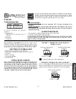
Page 15: ...s instructions et noter les informations se rapportant spécifiquement à votre produit CARACTÉRISTIQUES Les produits sont testés et approuvés par UL cUL et FCC IC La portée opérationnelle est de 30 mètres Lescommandesd éclairageHeath Zenithsontconçuespourfonctionnerensemble Il suffit de déterminer quel transmetteur doit commander quel récepteur puis de régler les codes correspondants Avertissement ...

Page 16: ...il extérieur Micro interrupteurs DETECT CODES 1 2 3 4 DAY NIGHT NIGHT ONLY ON 1 2 3 4 Vue rapprochée d un micro interrupteur réglage en usine à la position OFF Note Le X placé sur les micro interrupteurs vise à préciser la position à la page précédente Projecteur Micro interrupteurs ...

Page 17: ...ure à rotule sur le détecteur dans la douille du support de montage Note Vous devriez entendre un claquement Dirigez le détecteur vers la zone où vous voulez détecter le mouvement Serrez la vis de serrage IMPORTANT Le détecteur doit être monté avec le couvercle inférieur vers le bas afin d assurer l étanchéité Vérification du fonctionnement et du réglage Note Lorsque l appareil est mis en circuit ...

Page 18: ...e ON TIME Déterminez pendant combien de temps vous voulez que le dispositif connecté reste allumé après que le mouvement ait été détecté 1 ou 5 minutes Glissez la commande ON TIME vers le réglage correspondant IMPORTANT Évitez de diriger la commande vers Desobjetsquichangentrapidementdetempérature notamment évents de chauffage ventilateurs appareil de conditionnement de l air Ces sources de chaleu...

Page 19: ...tite extrémité du spport de plastique à travers le trou dans le centre de la plaque couvercle Insérez la petite extrémité dans une des fentes sur le support de montage 3 Acheminez les fils à partir du récepteur optique à travers les gros trous du joint 4 Torsadezlesfilsdudisjoncteuretlesfilsdel appareild éclairage tel qu illustré Fixez les à l aide des capuchons de connexion approuvés UL 5 Alignez...

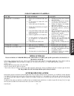
Page 20: ... éteint pas Le dispositif s allume au hasard SOLUTION 1 Vérifiezqueledisjoncteuroulefusible sont allumés 2 Vérifiez que l interrupteur sur le dispositif est allumé 3 Modifiez les codes du transmetteur et du récepteur 4 Attendez 90 secondes de période d initialisation détecteur de mouve ment à distance 5 Vérifiezs ilyadesobjetsmétalliques pouvant bloquer le signal ou reposi tionnez le transmetteur ...

Page 21: ...e dérangement l installation le réglage la perte d utilisation le service non autorisé ou les frais d expédition pour le renvoi de la marchandise La garantie ne couvre que les produits assemblés HeathCo LLC et ne s étend pas aux autres équipements et composants que le client pourrait utiliser conjointement avec nos produits CETTE GARANTIE TIENT EXPRESSÉMENT LIEU DE TOUTES AUTRES GARANTIES EXPLICIT...

Page 22: ..._______________________________ _____________________________________ _____________________________________ _____________________________________ _____________________________________ _____________________________________ _____________________________________ _____________________________________ _____________________________________ _____________________________________ __________________________...

Page 23: ..._______________________________ _____________________________________ _____________________________________ _____________________________________ _____________________________________ _____________________________________ _____________________________________ _____________________________________ _____________________________________ _____________________________________ __________________________...

Page 24: ...vor guarde su recibo de venta fechado se lo requiere para cualquier solicitud de garantía Veuillez conserver le reçu portant la date d achat vous en aurez besoin pour toutes vos demandes liées à la garantie Purchase Information Información de la compra Renseignements d achat Model _ _______________ Date of Purchase _ __________________ Nº de modelo N de modèle Fecha de compra Date d achat ...

Reviews: