


The Utile Engineering Co. Ltd.
11/08/06
Irthlingborough, Northamptonshire. England
Tel: +44 (0) 1933 650216
Fax: +44 (0) 1933 652738
6 IC154
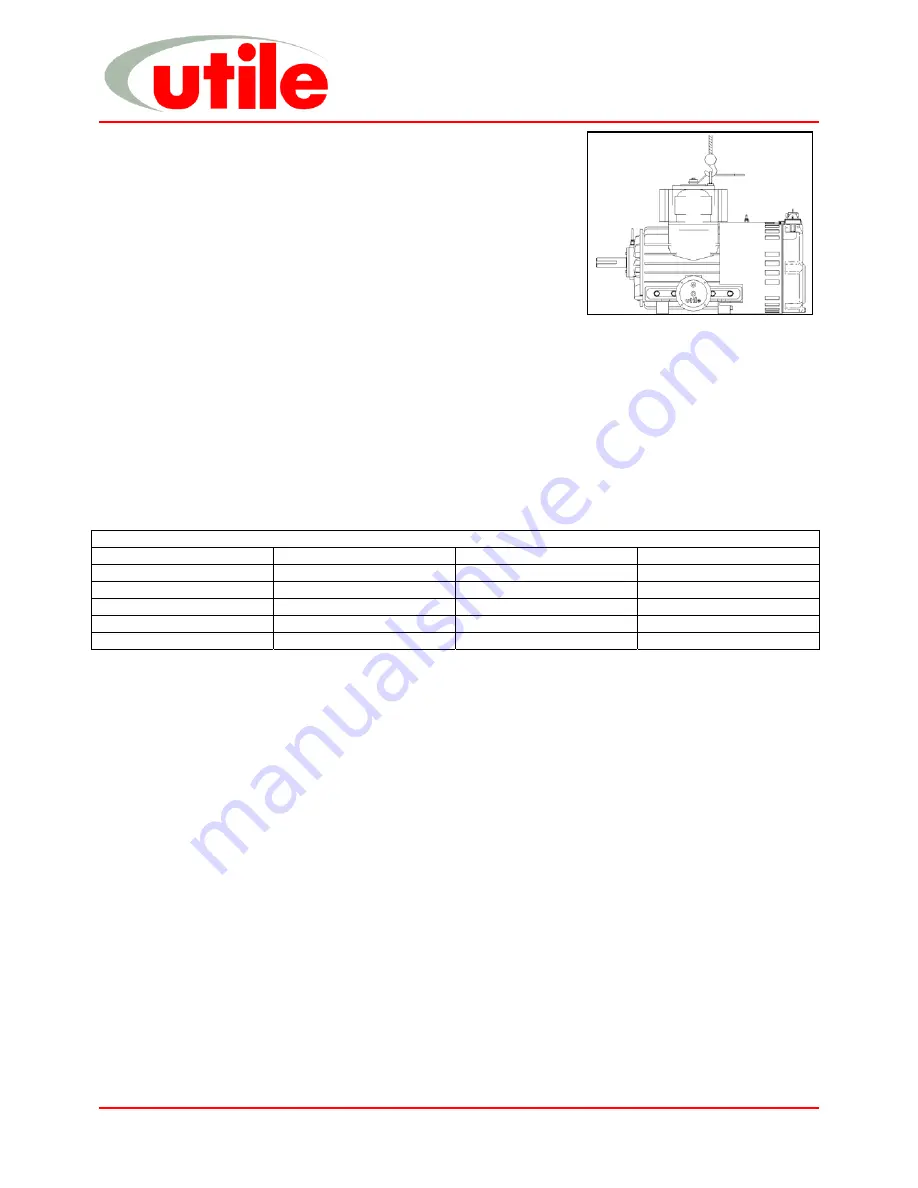
Handling
Skilled personnel working in accordance with safe working practices must
carry out the lifting of machines. Before lifting the correct equipment must
be available. Cranes, jacks, slings, and lifting beams must be capable of
carrying the weight of the machine to be lifted. The lifting eyebolt situated in
the top of the cylinder and a crane hook must be used when lifting or
moving the machine (see fig 3). Do not use the machine ports or the shaft
extension for lifting or moving the machine.
For weights see table in Technical Specification.
Installation
Before commencing installation, a site specific risk assessment, method statement and hazard identification list
must be completed and adhered to. All work must be carried out in a safe area. Utile Engineering trained personnel
or those trained to an equivalent standard should carry out installation, any claims for damage due to faulty
installation will be void. The machine is delivered ready to be connected, with only the removal of the intake and
discharge protection covers. All warning labels and instructions must be observed and retained with the machine.
Before installation, ensure there is no damage to the machine and that it turns freely by hand.
Typical tools required for installation include: -
Set of spanners
Pipe Wrenches Set
of
screwdrivers
Hacksaw
Set of Allen Keys
Hammer / mallet
Drill (low voltage)
Typical bolt tightening torques are: -
Bolt Tightening Torques
Size Torque Size Torque
M4
4.00 Nm
M12
70.00 Nm
M5 6.00
Nm M16
100.00
Nm
M6 10.00
Nm M20 150.00
Nm
M8 18.00
Nm M24 250.00
Nm
M10 40.00
Nm
Location
The machine should be installed in a clean, dry, well-ventilated area. Allow adequate space and facilities for
service, inspection and future expansion. A minimum of 0.75m of working space around the machine is
recommended. Adequate space around the motor and machine, particularly any fan inlets, is also necessary to
facilitate cooling airflow. Where several machines are installed in close proximity, care must be taken to ensure
there is no recirculation of exhausted warm air.
Foundation
Simple slab type foundations, designed for static loadings only are satisfactory. The foundations should raise the
machine to a reasonable height above the floor for convenient service and inspection. The use of anti-vibration
mounts between the base and foundation are recommended, these absorb the vibrations generated by the rotating
parts of the machine and insulate it against any vibration in the surrounding environment. Ensure that the anti-
vibration mounts are evenly loaded. Foundation bolts should fix the base.
Electrical Supply and Connection
The voltage rating of the supply must be compatible with the motor and the fittings. All electrical installation must be
carried out by a qualified electrician and in accordance with current regulations and within the framework of the
Electricity of Work Regulation 1990. Ensure all electrical connections, plugs, sockets etc are secure before
switching the supply on.
Earthing
It is important that the motor enclosure is soundly earthed by metallic earth continuity conductor, or by separate
earth bonding, but in all cases the installation must be made and tested and approved for this feature by a qualified
installer before the supply is applied to the motor.
Handling
Installation
Fig. 3


