background image

5

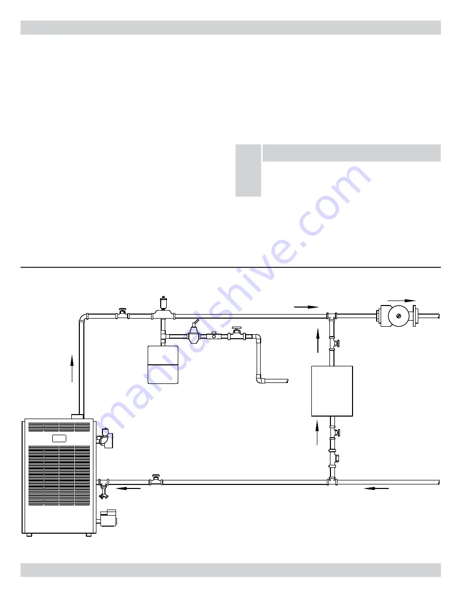
Connect supply and return piping as suggested in 

1. 

Fig-

ure #2

 below when the boiler is used in connection with 

refrigerated systems:

The chilled medium MUST BE IN PARALLEL with 

A. 

the boiler. 
Use appropriate valves to prevent the chilled medium 

B. 

from entering the heating boiler.
During heating cycle open valves A and B. Close 

t

valves C and D.
During cooling cycle open valves C and D, close valves 

t

A and B.
Maintain a minimum clearance of 1 inch (2.54 cm) to 

C. 

hot water pipes. In air handling units where they may 

be exposed to refrigerated air circulation, the boiler 

piping system MUST be supplied with flow control 

valves or other automatic means to prevent grav-

ity circulation of the boiler water during the cooling 

cycle.

CONNECTING SUPPLY AND RETURN PIPING

EXPANSION

TANK

B

A

D

CHECK

VALVE

CIRCULATOR

FROM HEATING

AND COOLING

ELEMENT

SUPPLY PIPING

TO HEATING

AND COOLING

ELEMENT

WATER

CHILLER

C

RETURN PIPING

FEED

WATER

NOTICE

* Reduced pressure back flow preventer must be used 

under provisions required by the Environmental Pro-

tection Agency, (EPA).

Hot water boilers installed above radiation level must be 

2. 

provided with a low water cut-off device at the time of 

boiler installation.
When a boiler is connected to a heating system that 

3. 

utilizes multiple zoned circulators, each circulator must 

be supplied with a flow control valve to prevent gravity 

circulation.

Figure 1 - Near Boiler Supply & Return Piping

National Excelsior Company 
www.excelsiorhvac.com

Subject to change without notice.

Summary of Contents for USC SERIES

Page 1: ... Boiler INSTALLATION OPERATION MAINTENANCE MANUAL MEMBER The Hydronics Institute UTICA BOILERS P O Box 4729 Utica NY 13504 4729 www uticaboilers com R An ISO 9001 2000 Certified Company National Excelsior Company www excelsiorhvac com Subject to change without notice ...

Page 2: ...ion of factory equipped supplied or specified components may result in property damage personal injury or the loss of life 4 To the owner Installation and service of this boiler must be performed by a qualified installer 5 To the installer Leave all instructions with the boiler for future reference 6 When this product is installed in the Common wealth of Massachusetts the installation must be per ...

Page 3: ... replacement of another appliance such as a water heater The boiler shall be installed such that the gas ignition 7 system components are protected from water drip ping spraying rain etc during appliance operation and service circulator replacement condensate trap control replacement etc 6 15 2 cm MIN 9 22 9 cm MIN 3 7 6 cm MIN 4 10 2 cm MIN FRONT OF BOILER WARNING Improper installation adjustment...

Page 4: ...rate of 4 for each 1 000 ft above sea level STANDARD EQUIPMENT Boiler Jacket Cast Iron Boiler Battery Limit Control Remov able Transformers Plug in Relay Theraltimeter Gauge Cir culator field mounted Main Gas Burners Hot Surface Pilot A S M E Relief Valve Drain Cock Induced Draft Fan Safety Pressure Switch and Combination Intake Exhaust Termina tion Kit All boilers are design certified for install...

Page 5: ...ns to prevent grav ity circulation of the boiler water during the cooling cycle CONNECTING SUPPLY AND RETURN PIPING EXPANSION TANK B A D CHECK VALVE CIRCULATOR FROM HEATING AND COOLING ELEMENT SUPPLY PIPING TO HEATING AND COOLING ELEMENT WATER CHILLER C RETURN PIPING FEED WATER NOTICE Reduced pressure back flow preventer must be used under provisions required by the Environmental Pro tection Agenc...

Page 6: ... 5 When using bypass piping adjust valves A and B in Figures 3 5 until desired system tempera ture is obtained NOTE 6 When using a 4 way mixing valve set control knob until desired temperatures are met See instruction supplied with valve Bypass loop piping must be the same 7 size piping as the supply and the return Typical installation using circulators 8 is shown in Figure 6 on following page Typ...

Page 7: ...IRCULATOR SYSTEM CIR REDUCED PRESSURE BACKFLOW PREVENTER FEED WATER SYSTEM RETURN COLD WATER PUMP CONTROL THERMOSTAT WIRING FOR TRAP THERMAL OUTLET HOT WATER DRAIN COCK RELIEF VALVE FLOW CONTROL INLET OR CHECK VALVE GATE VALVE PRESSURE REDUCING VALVE Figure 5 Primary Secondary Piping with Bypass Figure 6 National Excelsior Company www excelsiorhvac com Subject to change without notice ...

Page 8: ...ng systems are required for higher efficiency appliances CONNECTING SUPPLY AND RETURN PIPING GENERAL INFORMATION GAS VENTS AND APPLIANCES TANK ZONE VALVE SYSTEM ZONE VALVE CIR WATER FEED INLET COLD WATER HOT WATER OUTLET PUMP CONTROL WIRING FOR THERMOSTAT TRAP TERMAL RELIEF VALVE DRAIN COCK RETURN SYSTEM PRESSURE REDUCING VALVE BACKFLOW PREVENTER REDUCED PRESSURE GATE VALVE WARNING Vents for Categ...

Page 9: ...austs so they will oper ate at maximum speed Do not operate a summer exhaust fan Close fireplace dampers Place in operation the appliance being inspected Follow 4 the lighting instructions Adjust thermostat so appliance will operate continuously Test for spillage at the draft hood relief opening after 5 5 minutes of main burner operation Use the flame of a match or candle or smoke from a cigarette...

Page 10: ...hould be of adequate size to prevent undue 1 pressure drop and never smaller than the pipe size of the main gas control valve See chart below To check for leaks in gas piping use a soap and water 2 solution or other approved method WARNING DO NOT USE AN OPEN FLAME NOTICE For additional information refer to Part 10 table 10 2 of the National Fuel Gas Code Handbook latest revi sion or in Canada the ...

Page 11: ...imit Switch LS Circulator CIR Wire Connection Not all components listed are used in all control systems WIRING CODE KEY LINE VOLTAGE BY FACTORY LOW VOLTAGE BY FACTORY LINE VOLTAGE BY INSTALLER LOW VOLTAGE BY INSTALLER NOTICE t 4XJUDIFT BSF TIPXO JO QPTJUJPO EVSJOH UIF IFBUJOH cycle t G BOZ PG UIF PSJHJOBM XJSJOH TVQQMJFE XJUI UIF CPJMFS is replaced it must be replaced with like wire size and type ...

Page 12: ... SV9501H Q3450B ORANGE IGNITION CONTROL Honeywell ORANGE GREEN 120V 60HZ SUPPLY C INDUCED DRAFT BLOWER TH 2 1 4 3 6 CIR 1K1 1K2 1K L1 L2 C2 LM FT TV T VM VM C1 L4080B LS PS B NO LM GREEN AND WHITE SV9501H Q3450B Honeywell CONTROL IGNITION WHITE WHITE BLUE BLUE GREEN YELLOW YELLOW RED BLACK RED BLACK RED ORG BLUE BLUE ORG ORG National Excelsior Company www excelsiorhvac com Subject to change withou...

Page 13: ...O IF YOU SMELL GAS Do not try to light any appliance t Do not touch any electrical switch t D t o not use any phone in your building Immediately call your gas supplier from a neighbor s t phone Follow the gas supplier s instructions t If you cannot reach your gas supplier call the fire t department Use only your hand to move the system control switch 3 Never use tools If the switch will not move b...

Page 14: ...appliance 8 Set thermostat to desired setting 9 If the appliance will not operate follow the instructions 10 To Turn Off Gas To Appliance Below and call a quali fied service technician or your gas supplier SEQUENCE OF OPERATION system Power will remain off until the water temperature drops below the high limit setting The circulator will con tinue to operate under this condition until the thermost...

Page 15: ...ed service agency be employed to make an annual inspection of the boiler and the heating sys tem They are experienced in making the inspection outlined below In the event repairs or corrections are necessary they can make the proper changes for safe operation of the boiler Periodic cleaning of the condensate collection system is re quired When a condensate collection system is installed in a venti...

Page 16: ...ont panel See 2 figure 12 Disconnect the vent pipe from the vent pipe adapter 3 Disconnect the air inlet pipe from the coupling See 4 fig ure 13 for coupling location Remove the air box covers See 5 figure 13 Remove the burners from the combustion chamber by 6 raising the burners up from the manifold orifices and pull ing toward the front of the boiler See figure 14 Remove the top panel See 7 figu...

Page 17: ...tor using the hold down screws 13 and silicone in place with GE IS 808 silicone or similar See figure 15 Repeat steps A E in reverse order to reassemble the boiler 14 Start boiler to insure proper operating condition 15 KEEP the area around the boiler clean and free of combus 16 tible materials such as gasoline paints paint thinner and other such flammable vapors and liquids The free flow of combu...

Page 18: ...ch TO AIR BOX TAP TAP TO VENTER SWITCH WHITE TO PRESSURE HONEY WELL ON OFF TO PRESSURE SWITCH ORANGE The other part of the tee goes to the air box and venter 3 pressure taps Orange being the high negative A White being the low negative B Turn the boiler back on and read the static pressure The 4 reading should be 55 05 inches water column or higher for the Sealed Combustion series boilers If the s...

Page 19: ... C heating value of the gas as obtained from the lo cal gas company This will determine the number of cubic feet of gas required per hour If minor adjustment is necessary install a manometer D on the outlet side of the gas valve Adjust the pressure regulator on the combination gas control Increase or decrease manifold pressure to obtain gas input required as described on the rating plate To increa...

Page 20: ...s Code Part 7 NFPA ANSI211 Chimneys Fireplaces Vents and Solid Fuel Burning Appliances CANADA CAN1 B149 1 Installation Codes for Gas Burning Equipment B149 2 Installation Codes for Gas Burning Equipment These codes contain information on special gas vents for Category II III and IV appliances vent sizing lo cation air space clearances to combustibles and safe installation practices The gas vent in...

Page 21: ...l space or an attic the hard wired carbon monoxide detector with alarm and battery back up may be installed on the next adjacent floor level In the event that the requirements of this subdivision B can not be met at the time of completion of installa tion the owner shall have a period of thirty 30 days to comply with the above requirements provided however that during said thirty 30 day period a b...

Page 22: ...stallation can allow toxic fumes to be re leased into living areas This may cause serious bodily injury or property damage Vent performance may also be affected by improper assembly Install separate vents for forced exhaust appliances and natural draft appliances A common vent between natural draft and forced exhaust appliances may cause toxic gases to exhaust through the natural draft ap pliance ...

Page 23: ...l vent lengths exceed 10 feet 2 Insert vent pipe in boiler venter outlet vent adapter apply silicone completely around edge of outlet and tighten clamp Figure 2 HORIZONTAL VENT PIPING TYPICAL INSTALLATION National Excelsior Company www excelsiorhvac com Subject to change without notice ...

Page 24: ...xpelled near unprotected surfaces Sealing or shielding of H exposed surfaces with a corrosion resistant material such as aluminum sheet may be required to prevent staining or deterioration When installing vent cap secure it to a noncombustible wall or a combustible wall thimble Fasten vent cap and seal pas I sage as shown in figures 3 5a and 5b See the National or Canadian Codes listed at the begi...

Page 25: ...g and secure it to the outside wall 5 Install the PVC pipe from the vent termination assembly to the boilers air inlet 6 Assemble and install the vent pipe according to the vent pipe manufacturers instructions 7 Install the vent pipe through the termination assembly and extend it 3 7 6 cm beyond the termination assembly 8 See figures 5a and 5b Install the termination wind deflector with the four 4...

Page 26: ...ation Kit And Wall For Combustible Wall Installation Figure 5b Top View Of Termination Kit And Wall For Non Combustible Wall Installation Remove Thimble wall Plate Assembly National Excelsior Company www excelsiorhvac com Subject to change without notice ...

Page 27: ...1 cm ID tubing or a 9 22 9 cm diameter loop in 5 8 1 6 cm ID tubing Secure the loop with a plastic cable tie Run the other end of the flexible tubing to a sanitary drain Use a condensate pump if necessary Fill loop with water before firing the boiler THIMBLE VENT PIPE CONDENSATE DRAIN TERMINATION TEE CONDENSATE TRAP ASSY NOTE REFER TO VENT PIPE LENGTHS FOR USAGE VENT 12 30 5 cm MINIMUM TEE Figure ...

Page 28: ... LOCATE VENT CAP TO ALLOW 12 31 CM MIN ABOVE GRADE VENT CAP MUST BE AT LEAST 12 31 CM HORIZONTALLY FROM ANY ELECTRIC METERS GAS METERS OR RELIEF EQUIPMENT NOTE IF THERE IS A POTENTIAL FOR EXCESSIVE WINDS SPECIAL CONSIDERATION SHOULD BE GIVEN TO LOCATE THE VENT TERMINATION AWAY FROM THE WINDWARD SIDE OF THE BUILDING Figure 9 Vent Clearances When multiple boilers are used a clearance of 12 31 ccm is...

Page 29: ...ntal vent lengths exceed 10 feet 2 Insert vent pipe in boiler venter outlet vent adapter apply silicone completely around edge of outlet and tighten clamp Figure 10 Flex L Star 34 Vent Pipe Components National Excelsior Company www excelsiorhvac com Subject to change without notice ...

Page 30: ...al vent lengths exceed 10 feet 2 Insert vent pipe in boiler venter outlet vent adapter apply silicone completely around edge of outlet and tighten clamp Figure 11 Heat Fab Saf T Vent Vent Pipe Components National Excelsior Company www excelsiorhvac com Subject to change without notice ...

Page 31: ...ontal vent lengths exceed 10 feet 2 Insert vent pipe in boiler venter outlet vent adapter apply silicone completely around edge of outlet and tighten clamp Figure 12 Z Flex Z vent Vent Pipe Components National Excelsior Company www excelsiorhvac com Subject to change without notice ...

Page 32: ...tal vent lenghts exceed 10 feet 2 Insert vent pipe in boiler venter outlet vent adapter apply silicone completely around edge of outlet and tighten clamp Figure 13 ProTech FasNSeal Vent Pipe Components National Excelsior Company www excelsiorhvac com Subject to change without notice ...

Page 33: ... pipe in boiler venter outlet vent adapter apply silicone completely around edge of outlet and tighten clamp Figure 14 Vertical Vent Piping Typical Installation National Excelsior Company www excelsiorhvac com Subject to change without notice ...

Page 34: ...of vent air intake see 2 figure 16 Vent Pipe Lengths Vent Pipe Diameter 3 7 6 cm t Max Vent Length 30 ft 914 cm with 1 vertical drain tee 1 90 Elbow and 1 Termination Cap 5 Ft 152 cm Max t Horizontal Minimum Vent Length 2 ft 61 cm t Inlet Pipe 30 ft 914 cm Max 2 ft 61 cm Min 4 90 Elbows including intake 90 Elbow on Roof t INSTALLATION PROCEDURE FOR VERTICAL VENTING WARNING do not insulate or other...

Page 35: ... INSTRUCTIONS 35 Figure 17 Termination 10 Ft 305 cm Or Less From Ridge Figure 18 Termination More than 10 Ft 305 cm from Ridge National Excelsior Company www excelsiorhvac com Subject to change without notice ...

Page 36: ...36 VENTING INSTRUCTIONS Figure 19 Flex L Star 34 Vent Pipe Components National Excelsior Company www excelsiorhvac com Subject to change without notice ...

Page 37: ...VENTING INSTRUCTIONS 37 Figure 20 Z Flex Z vent Vent Pipe Components National Excelsior Company www excelsiorhvac com Subject to change without notice ...

Page 38: ...38 VENTING INSTRUCTIONS Figure 21 Heat Fab Saf T Vent Vent Pipe Components National Excelsior Company www excelsiorhvac com Subject to change without notice ...

Page 39: ...VENTING INSTRUCTIONS 39 Figure 20 ProTech FasNSeal Vent Pipe Components National Excelsior Company www excelsiorhvac com Subject to change without notice ...

Page 40: ...b 1039 HW NAT For Natural Gas Only 1 PB01402 Pilot Q3450b 1112 LP For Propane Gas Only 2 3771101 Pilot Assembly 1 3 HW 024 01 Screw 10 32x3 16 1 4 43300201 Pilot Tube 1 4 X24 1 4 Aluminum 1 PILOT National Excelsior Company www excelsiorhvac com Subject to change without notice ...

Page 41: ...60002 Pip Fit Bushing 3 4 X 1 4 1 7 43300976 Nipple 2 Mach 3 Section 4 Nipple 2 Mach 4 Section 6 Nipple 2 Mach 5 Section 8 8 3472301 Flue Collector Baffle 3 Section 4 Flue Collector Baffle 4 Section 6 Flue Collector Baffle 5 Section 8 9 HW 008 01 Wash 5 16 Flat Stl Zp 4 10 HW 003 02 Nut 1 4 20 Hex Stl Zp 2 FULLY ASSEMBLED HEAT EXCHANGERS 100 2 7 01 Heat Exchanger 3 Section 100 2 7 02 Heat Exchange...

Page 42: ...EM PART DESCRIPTIONS QTY 5 3272101 Air Box Wrapper 3 Section 1 3272102 Air Box Wrapper 4 Section 3272103 Air Box Wrapper 5 Section 6 240007769 Pilot Grommet 1 7 HW10201 Manifold Grommet 1 8 3271901 Air Box Wrapper Gskt Bot 3 Section 2 3271902 Air Box Wrapper Gskt Bot 4 Section 3271903 Air Box Wrapper Gskt Bot 5 Section 9 3271801 Air Box Wrapper Gasket 2 10 FOR NATURAL GAS ONLY VG01701 GAS VALVE SV...

Page 43: ...ssy 5 Section Includes Obs Window 9 Insul 11 ITEM PART DESCRIPTIONS QTY 8 3572401 Insul Frt Cov 3 Section 1 3572402 Insul Frt Cov 4 Section 3572403 Insul Frt Cov 5 Section 9 HW10001 Air Box Tap 2230 Rl 1 10 3572304 Insul Air Box Cover 2 11 3272401 Air Box Cover Assy 3 Section 1 3272402 Air Box Cover Assy 4 Section 3272403 Air Box Cover Assy 5 Section Includes Insulation 12 13 And Air Box Tap 6 Was...

Page 44: ...1510001 PIPE FIT TEE 1 1 4X3 4X1 1 4 1 6 PF 006 01 PIPE FIT NIPPLE 1 1 4 CLOSE 1 7 37518901 HARNESS CONTROL TO LIMIT 1 8 1260006 GAUGE THERALTIMETER 1 9 AQ02201 CONTROL LIMIT L4080B 1212 HW 1 10 AQ 020 01 WELL 3 4 X 3 HW 1 11 VR 001 01 RELIEF VALVE 30 3 4 1 12 1190001 PIPE FIT ELBOW 3 4 NPT 90 1 13 1310001 PIPE NIPPLE 3 4 X 4 NPT 1 REPLACEMENT PARTS National Excelsior Company www excelsiorhvac com...

Page 45: ... R8222C 1008 1 5 HW09601 TUBING SILICON CLEAR 12 6 EF04001 9 TERM STRIP 1 7 HW09701 TUBING SILICON ORANGE 17 8 HW09001 SCREW 10 32X5 16 GREEN GROUND 1 9 3172701 PANEL CONTROL SUPPORT BRACKET 1 3772201 COMPLETE CONTROL BRACKET ASSEMBLY THIS INCLUDES PART 1 2 3 5 7 8 ALL WIRING 1 REPLACEMENT PARTS National Excelsior Company www excelsiorhvac com Subject to change without notice ...

Page 46: ... FLUE COLLECTOR ASSY 4 Section 3472503 FLUE COLLECTOR ASSY 5 Section 2 345 2 7 01 VENT ADAPTER 1 3 HW 005 01 SCREW 1 4 20X1 2 SELF TAP 5 4 DC00402 VENTER JAKEL 1 5 3571501 GASKET VENTER 1 6 HW09501 BOLT 5 16 18X1 1 2 TYPE F 2 REPLACEMENT PARTS National Excelsior Company www excelsiorhvac com Subject to change without notice ...

Page 47: ... 34721401 VENT TERMINATION DEFLECTOR 1 4 1330006 NUT 10 24 HEX 1 5 30A004312 SCREW 10 24 X 1 1 2 ROUND HEAD 1 6 3471701 DRAW COLLAR 1 7 HW 009 01 SCR 8 18X1 2 SLT HX WASH 8 8 3471901 VENT TEMPLATE 1 5612601 TERMINATION KIT INCLUDES ALL OF THE ABOVE REPLACEMENT PARTS National Excelsior Company www excelsiorhvac com Subject to change without notice ...

Page 48: ... 3172402 Panel Separator Plate 4 Section 3172403 Panel Separator Plate 5 Section 4 31721101 Panel Right Hand Side 1 5 31721401 Panel Rear 3 Section 1 31721402 Panel Rear 4 Section 31721403 Panel Rear 5 Section 6 3172201 Panel Top 3 Section 1 3172202 Panel Top 4 Section 3172203 Panel Top 5 Section 6 1 2 3 4 5 REPLACEMENT PARTS National Excelsior Company www excelsiorhvac com Subject to change witho...

Reviews: