19
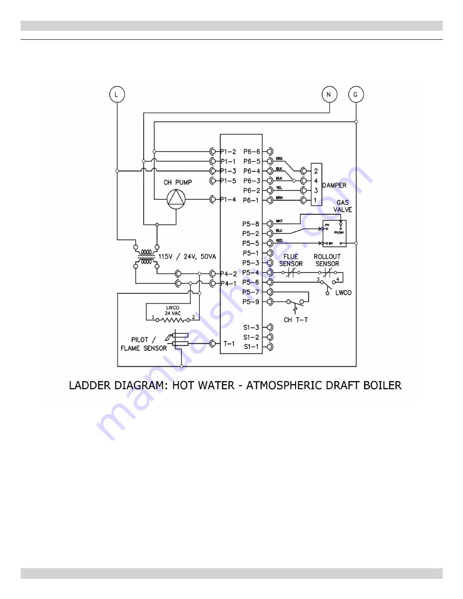
11 - WIRING DIAGRAM
Figure 13
- Integrated High Limit & Electronic Ignition Control
PN 240011107, Rev. E [06/15/2018]
Page 1: ...st Iron Gas Fired Boilers For Forced Hot Water INSTALLATION OPERATION MAINTENANCE MANUAL Tested For 100 psi ASME Working Pressure C S A Certified For Natural Gas Or Propane Manufactured by ECR International Inc 2201 Dwyer Avenue Utica NY 13501 Tel 800 253 7900 www ecrinternational com PN 240011107 REV E 06 15 2018 ...
Page 2: ...above sea level United States over 2000 ft 610m above sea level Reduce input rate 4 for every 1 000 ft 304m above sea level 2 Net AHRI Water Ratings shown based on piping and pickup allowance of 1 15 Consult manufacturer before selecting boiler for installations having unusual piping and pickup requirements such as intermittent system operation extensive piping systems etc For forced hot water sys...
Page 3: ...5 28 2015 16 415 16 1 UH15B096 15 7 5 28 2015 16 415 16 1 UH15B120 19 9 6 29 217 16 57 16 1 UH15B145 19 9 6 29 217 16 57 16 1 UH15B170 22 113 16 7 30 2115 16 515 16 1 UH15B195 22 113 16 7 30 2115 16 515 16 1 UH15B245 26 136 16 8 31 227 16 615 16 1 UH15B295 30 155 16 9 32 2215 16 815 16 1 Propane Gas Inlet All Units 1 2 FRONT OF BOILER Dimensions Rear Front 3 1 RETURN 3 TOP OF BOILER LEFT SIDE OF B...
Page 4: ...iring Diagram 18 12 Lighting Instructions 20 13 Normal Sequence of Operation 21 14 General Instructions 21 15 Checking Gas Input Rate To Boiler 23 APPENDIX A CONTROL MODULE A 1 Installation Environment Considerations 24 A 2 Electrical Connections 24 A 3 Adjusting Settings 24 A 4 Display 24 A 5 Operation 25 A 6 Boiler High Limit Temperature Controller 27 A 8 Troubleshooting Error Codes 27 A 9 Inter...
Page 5: ...ENCE WARNING Keep boiler area clear and free from combustible materials gasoline and other flammable vapors and liquids DO NOT obstruct air openings to the boiler room Modification substitution or elimination of factory equipped supplied or specified components may result in personal injury or loss of life TO THE OWNER Installation and service of this boiler must be performed by a qualified instal...
Page 6: ...ng rain etc during appliance operation and service circulator replacement condensate trap control replacement etc 6 Locate boiler on level solid base as near chimney as possible and centrally located with respect to heat distribution system as practical 7 When installed in utility room door should be wide enough to allow largest boiler part to enter or to permit replacement of another appliance su...
Page 7: ...tion rate is less than 0 40 air changes per hour See Table 3 for space with boiler only Use equation for multiple appliances Volume 50 ft3 x Total Input Mbh о о Known Air Infiltration Rate See Table 3 for space with boiler only Use equation for multiple appliances Do not use an air infiltration rate ACH greater than 0 60 Volume 21 ft3 ACH x Total Input Mbh о о Refer to National Fuel Gas Code for o...
Page 8: ...than 3 time safety relief valve pressure settings Do not install shutoff valve between boiler and safety relief valve Systems with automatic fill valves require back flow prevention device Install discharge piping from safety relief valve See Warning Page 8 When boiler is connected to heating system utilizing multiple zoned circulators each circulator must be supplied with flow control valve to pr...
Page 9: ...lowable safe point of discharge be of pipe size equal to or greater than that of the relief valve outlet over the entire length of discharge line have no intervening shutoff valve between safety relief valve and discharge to atmosphere do not plug or place any obstruction in discharge line terminate freely to atmosphere where any discharge will be clearly visible and at no risk of freezing allow c...
Page 10: ...ENT CIRCULATOR A PRESSURE REDUCING VALVE PROPER BACKFLOW PROTECTION DEVICE GATE VALVE PURGE VALVE NOTICE Circulators in following illustrations are mounted on system supply side mounting on system return side is also acceptable practice Figure 2 Circulators Mounted on Supply System Boiler Used In Configuration to Chiller System See Special Conditions Page 8 PN 240011107 Rev E 06 15 2018 ...
Page 11: ...ee Bypass Piping Options Page 8 BOILER WATER INLET ALTERNATE CIRCULATOR LOCATION TO SYSTEM FROM SYSTEM CIRCULATOR SHUT OFF VALVE PRESSURE REDUCER VALVE CHECK VALVE BALL VALVE 3 WAY MIXING VALVE AIR SEPARATOR HOSE BIB EXPANSION TANK Note Bypass connection not showing primary secondary piping Note Bypass connection not showing primary secondary piping PN 240011107 Rev E 06 15 2018 ...
Page 12: ...12 5 CONNECTING SUPPLY AND RETURN PIPING Figure 5 Single Zone System With DHW Priority Figure 6 Multi Zone System with Circulators and DHW Priority PN 240011107 Rev E 06 15 2018 ...
Page 13: ...TING SUPPLY AND RETURN PIPING Figure 7 Multi zone System With Zone Valves And DHW Priority With Circulator Figure 8 Multi zone System With Zone Valves And DHW Priority With Zone Valve PN 240011107 Rev E 06 15 2018 ...
Page 14: ...rtion of the common venting system the common venting system should be re sized to approach the minimum size determined using the appropriate tables in Chapter 13 of the National Fuel Gas Code ANSI Z223 1 NFPA 54 and or the Natural Gas and Propane Installation Code CAN CSA B149 1 1 Vent pipe must slope upward from boiler not less then inch per 1 foot to the vent terminal 2 Horizontal portions of v...
Page 15: ... match total current draw of all controls associated with boiler during heating cycle 8 VENT DAMPER INSTALLATION INSTRUCTIONS Figure 9 Damper Installation Figure 10 Damper Location NOTE Refer to Figure 9 for steps 1 6 1 Place Vent Damper on or as close to vent outlet of boiler as possible Do not modify draft hood or vent damper during installation 2 Remove Vent Damper Motor cover 3 Feed damper wir...
Page 16: ...iping with hooks straps bands brackets hangers or building structure components to prevent or dampen excessive vibrations and prevent strain on gas connection Boiler will not support piping weight Use thread joint compound pipe dope suitable for liquefied petroleum gas Install field sourced manual main shutoff valve ground joint union and sediment trap upstream of gas valve See Figure 11 Table 5 G...
Page 17: ...ector Use low voltage harness 2 Vent damper connection 3 Circulator connection 4 Line power connections 5 Thermostat connection See wiring diagrams on the following two pages for details Thermostat Installation 1 Install thermostat on inside wall about four feet above floor 2 NEVER install thermostat on outside wall 3 Do not install a thermostat where it will be affected by drafts hot or cold pipe...
Page 18: ... 12 Integrated High Limit Electronic Ignition Control WARNING Modification substitution or elimination of factory equipped supplied or specified components may result in personal injury or loss of life PN 240011107 Rev E 06 15 2018 ...
Page 19: ...19 11 WIRING DIAGRAM Figure 13 Integrated High Limit Electronic Ignition Control PN 240011107 Rev E 06 15 2018 ...
Page 20: ... Off Gas To Appliance and call qualified service technician or your gas supplier TO TURN OFF GAS TO THE APPLIANCE 1 Set the thermostat to lowest setting 2 Turn off all electric power to the appliance if service is to be performed 3 Push in gas control knob slightly and turn clockwise to OFF DO NOT FORCE 4 Call qualified service technician WARNING If you do not follow these instructions exactly a f...
Page 21: ...have them repaired immediately Check and maintain circulators Refer to circulator manufacturer s instructions Inspect venting system at the start of each heating season Check vent pipe from boiler to chimney for signs of deterioration by rust or sagging joints Repair if necessary Remove vent pipe at base of chimney or flue and using mirror check vent for obstruction and verify vent is in good work...
Page 22: ...gns of corrosion rust or scale buildup Area around boiler must be kept clear and free of combustible materials gasoline and other flammable vapors and liquids Free flow of combustion and ventilating air to boiler and boiler room must not be restricted or blocked Inspect field sourced low water cutoffs annually or as recommended by low water cutoff manufacturer Flush float type low water cutoffs pe...
Page 23: ...ot necessary therefore air shutters are not furnished as standard equipment Air shutters can be furnished on request where required by local codes or conditions CHECK SAFETY CONTROL CIRCUIT Ignition system safety shutoff device must be tested after placing boiler in operation Intermittent Pilot With main burner operating turn pilot gas adjusting screw clockwise until pilot gas is turned off See Fi...
Page 24: ...g transit Check sensing bulb is fully inserted in well and is not loose Verify vent damper connection is made See page 15 A 3 Adjusting Settings To discourage unauthorized changing of settings procedure to enter adjustment mode is required To enter adjustment mode press UP DOWN and I buttons simultaneously for three seconds Press and release I button until parameter requiring adjustment is display...
Page 25: ...t is open a switch closes to do this The control is waiting for this to occur This may last up to one minute If the vent damper switch has not closed after one minute ERR 55 will be displayed e 17 Diagnostics Another diagnostic check The control will also check the safety switches rollout and vent are closed This will be so quick the control may move on before the STA code is flashed Should the sa...
Page 26: ...are the only two 2 hard lockouts on this model m 15 Wait for limit to close One of the safety limits rollout vent spill or low water cutoff has been activated Control will resume normal operation once limit is reset Underlying cause why the limit switch opened MUST be investigated n 16 Flame out of sequence Flame signal sensed before trial ignition Appropriate alarm is sent OR Flame signal sensed ...
Page 27: ...ay On retry models wait for retry or reset at thermostat Check for correct installation and wiring before replacing any component Control module cannot be repaired If it malfunctions it must be replaced Use only qualified service agent to service ignition systems 1 Perform checkout as first step in troubleshooting Check troubleshooting guide to pinpoint cause of problem See Table 7 page 28 2 If tr...
Page 28: ... providing expected reading 1 Check sensor is plugged into control board 2 Check sensor wiring is not damaged 3 Scroll display reading to bt and hold sensor bulb securely in you hand It should read a temperature close to body temperature If not replace sensor 55 Damper end switch failed to close Vent damper must confirm it is open switch closes to do this Control did not receive this signal after ...
Page 29: ...2095 1 Check gas valve gas supply 2 Check all electrical connections are tight 3 Check pilot rod is clean 4 Check for adequate draft 5 Check for adequate combustion air 64 Soft Lockout Internal failure Control is sensing something wrong with electrical circuitry 1 Check all wiring is correct Refer to wiring diagram 2 Check there is a good ground to pilot bracket 65 Hard Lockout Temperature above l...
Page 30: ... is required for module and pilot burner igniter sensor Check for good metal to metal contact between pilot burner bracket and the main burner Check ground lead from GND BURNER terminal on module to pilot burner Verify connections are clean and tight If wire is damaged or deteriorated replace with No 14 18 gauge moisture resistant thermoplastic insulated wire with 105 C 221 F minimum rating Check ...
Page 31: ...heck for cracked ceramic insulator which can cause short to ground and replace igniter sensor if necessary At gas valve disconnect main valve wire from MV terminal Turn on power and set thermostat to call for heat Pilot should light main burner will remain off because main valve actuator is disconnected Check pilot flame Verify it is blue steady and envelops 3 8 to 1 2 in 10 to 13 mm of flame rod ...
Page 32: ...r AC volts 24 volts should be present i IF NOT source of the problem is not in damper check line voltage and 24 volt supply ii If 24 volts is present across brown and black continue to step iii iii Reconnect thermostat wires and turn up heat setting iv Check voltage across black and orange wires in Molex plug 24 volts AC should be present IF NOT source problem is not the damper If 24 volts is pres...
Page 33: ...le Cause Recommended Solution NO POWER Between 4 1 1 Off on limit 120VAC 2 Bad transformer 3 Loose or broken connections 4 Blown fuse or circuit breaker 5 Disconnect switch off 6 Harness not plugged into receptacle 1 turn limit on 2 Replace transformer 3 Tighten repair or replace connection 4 Replace fuse or reset circuit breaker 5 Turn switch on 6 Plug harness in NO POWER Between 4 2 POWER Betwee...
Page 34: ...r the obstruction 2 Restore to damper pipe to round verify not binding 3 Correct the condition Damper Rotates Continuously 1 Defective damper motor assembly 1 Replace damper motor assembly Note For troubleshooting only Verify damper is in open position Use service switch to keep damper in open position Place jumper between 2 3 If appliance fires remove jumper and plug receptacle back into damper c...
Page 35: ...35 Company Address Phone Company Name Tech Initials Service Performed Date SERVICE RECORD PN 240011107 Rev E 06 15 2018 ...
Page 36: ... decreases This feature is equipped with an override which is provided primarily to permit the use of an external energy management system that serves the same function THIS OVERRIDE MUST NOT BE USED UNLESS AT LEAST ONE OF THE FOLLOWING CONDITIONS IS TRUE An external energy management system is installed that reduces the boiler water temperature as the heating load decreases This boiler is not use...