background image

16

6 - CHIMNEY AND VENT PIPE CONNECTION

Connecting The Vent Damper And Vent Connector

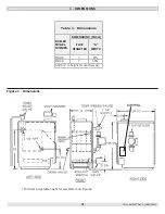
Refer to Figure 1, page 4 for size and location of vent (flue 

opening). 
 

NOTICE

Damper blade on furnished vent damper has 1/2 

square inch hole (approximately 3/4” diameter). 

Boilers equipped with intermittent ignition, hole 

should be plugged by using plug supplied with vent 

damper.

1. 

Position furnished vent damper on top of flue outlet 

collar. Fasten damper securely to flue outlet collar with 

sheet metal screws. Verify damper blade has clearance 

to operate inside of diverter. Do not modify either draft 

diverter or vent damper during installation.
As An Option
Damper may be installed in horizontal or vertical 

position, closer to flue outlet collar preferred. See 

Figures 8, 9 and 10 and enclosed vent damper 

instructions.

2. 

Install vent damper to service only single boiler for 

which it is intended. Damper position indicator shall be 

in visible location following installation. Locate damper 

so it is accessible for servicing. See Figure 9.

3. 

Damper must be in the open position when appliance 

main burners are operating.

4. 

Boiler is equipped with factory wired harness that plugs 

into vent damper.

5. 

Slope pipe up from boiler to chimney not less than 1/4” 

per foot.

6. 

Run pipe as directly as possible with as few elbows as 

possible.

7. 

Do not connect to fireplace flue.

8. 

End of vent pipe must be flush with inside face of 

chimney flue. Use a sealed-in thimble for chimney 

connection.

Fasten sections of vent pipe with sheet metal screws to 

make piping rigid. Support horizontal potions of vent 

system to prevent sagging. Use stovepipe wires every 5’ to 

support pipe from above. Use double wall vent pipe if vent 

pipe must go through crawl space. Where vent pipe passes 

through combustible wall or partition, use ventilated metal 

thimble. Thimble should be 4 inches larger in diameter than 

vent pipe.

Removing Existing Boiler From Common Venting 

System

When an existing boiler is removed from common venting 

system, common venting system is likely to be too large for 

proper venting of appliances remaining connected to it.

At time of removal of existing boiler, following steps shall 

be followed with each appliance remaining connected to the 

common venting system placed in operation, while other 

appliances remaining connected to common venting system 

are not in operation.

1. 

Seal any unused openings in the common venting 

system.

2. 

Visually inspect the venting system for proper size and 

horizontal pitch and determine there is no blockage or 

restriction, leakage, corrosion and other deficiencies 

which could cause an unsafe condition.

3. 

Insofar as is practical, close all building doors and 

windows and all doors between the space in which the 

appliances remaining connected to the common venting 

system are located and other spaces of the building. 

Turn on clothes dryers and any appliance not connected 

to the common venting system. Turn on any exhaust 

fans, such as range hoods and bathroom exhausts, so 

they will operate at maximum speed. Do not operate a 

summer exhaust fan. Close fireplace dampers.

4. 

Place in operation the appliance being inspected. Follow 

the lighting instructions. Adjust thermostat so appliance 

will operate continuously.

5. 

Test for spillage at the draft hood relief opening after 

5 minutes of main burner operation. Use the flame of 

a match or candle, or smoke from a cigarette, cigar or 

pipe.

6. 

After it has been determined that each appliance 

remaining connected to the common venting system 

properly vents when tested as outlined above, return 

doors, windows, exhaust fans, fireplace dampers and 

any other gas-burning appliance to their previous 

conditions of use.

7. 

Any improper operation of the common venting system 

should be corrected so the installation conforms with 

the National Fuel gas Code, ANSI Z223.1/NFPA 54, 

and/or the Natural Gas and Propane Installation Code, 

CAN/CSA B149.1.  When re-sizing any portion of the 

common venting system, the common venting system 

should be re-sized to approach the minimum size 

determined using the appropriate tables in Chapter 13 

of the National Fuel Gas Code, ANSI Z223.1/NFPA 54, 

and/or the Natural Gas and Propane Installation Code, 

CAN/CSA B149.1.

 WARNING

Do not connect boiler to any portion of mechanical 

draft system operating under positive pressure.

!


PN 240013087 Rev. A [09/30/2020]

Summary of Contents for MGC 3 Series

Page 1: ...ION MAINTENANCE MANUAL Manufactured by ECR International Inc 2201 Dwyer Avenue Utica NY 13501 Tel 800 253 7900 www ecrinternational com PN 240013087 REV A 09 01 2020 C S A Certified For Natural Gas Or Propane Tested For 50 psi ASME Working Pressure Models MGC 8D MGC 8DP MGC 9D MGC 9DP ...

Page 2: ...mation and specifications outlined in this manual in effect at the time of printing of this manual ECR International reserves the right to discontinue change specifications or system design at any time without notice and without incurring any obligation whatsoever Items found in parts box included with your boiler KEEP THIS MANUAL NEAR BOILER RETAIN FOR FUTURE REFERENCE For Parts lists see manual ...

Page 3: ...Supply Piping 18 9 Electrical Wiring 19 10 Wiring Diagram 20 11 General Instructions 21 12 Lighting Instructions 22 13 Operating Your Boiler 23 14 Service Hints 26 15 Maintaining Your Boiler 27 16 Boiler Ratings And Capacities 28 Appendix A Control Function 29 Appendix A Control Module 30 Appendix A 1 Vent Damper Harness 32 Appendix A 2 Vent Damper Troubleshooting 33 TABLE OF CONTENTS PN 240013087...

Page 4: ... Dimensions Minimum acceptable height for Low Water Cutoff probe PN 240013087 Rev A 09 30 2020 Table 1 Dimensions BOILER MODEL NUMBER DIMENSIONS INCH FLUE DIAMETER A WIDTH MGC 8 7 27 MGC 9 7 30 Add 5 to height for vent Damper ...

Page 5: ...tand all requirements before beginning installation FOR YOUR SAFETY READ BEFORE OPERATING Hot Water Can Scald Water heated to temperature for clothes washing dish washing and other sanitizing needs can scald and cause permanent injury Children elderly and infirm or physically handicapped persons are more likely to be permanently injured by hot water Never leave them unattended in bathtub or shower...

Page 6: ... be found on the NIOSH website https www cdc gov niosh topics silica NIOSH approved respirators manufacturers and phone numbers are also listed on this website Wear long sleeved loose fitting clothing gloves and eye protection Apply enough water to the combustion chamber lining to prevent dust Wash potentially contaminated clothes separately from other clothing Rinse clothes washer thoroughly NIOS...

Page 7: ...hting and other performance criteria with the gas manifold and control assembly on the boiler per the latest revision of ANSI Z21 13 CGA 4 9 5 Install boiler such that gas ignition system components are protected from water dripping spraying rain etc during appliance operation and service circulator replacement condensate trap control replacement etc 6 Locate boiler on level solid base as near chi...

Page 8: ...loric acid muriatic acid Cements adhesives and glues Photo processing plants Garages with workshops Furniture refinishing areas and establishments Laundry Chemicals Laundry detergents bleaches fabric softeners etc Antistatic fabric softeners dryer sheets Dry cleaning laundry areas and establishments Other Permanent wave solutions Refrigerants Freon etc only where the refrigerant may be leaking fro...

Page 9: ...piping Size and arrange discharge piping to avoid reducing safety relief valve relieving capacity below minimum relief valve capacity stated on rating plate Run pipe as short and straight as possible to location protecting user from scalding and properly drain piping Install union if used close to safety relief valve outlet Install elbow s if used close to safety relief valve outlet and downstream...

Page 10: ...er heating system become inoperative due to a power outage safety lockout or component failure 4 4 Water Treatment Manufacturer recommends a water analysis be done on water used to fill the system Treatment may be required based on the analysis results For extremely hard water or pH below 7 0 consult your local water treatment company Manufacturer recommends a water analysis be done on water used ...

Page 11: ... damage to boiler and venting system Minimum design return water temperature to prevent condensation in boiler and venting is 120 F Minimum high limit setting is 140 F 1 Boiler used in heating system where design water temperatures below 140 F are desired e g radiant floor heating 4 way mixing valve or suitable alternative is required to prevent low temperature return water from entering boiler Fo...

Page 12: ...12 Figure 5 Chilled Water Piping Figure 4 Typical Hot Water Piping 4 CONNECTING SUPPLY AND RETURN PIPING PN 240013087 Rev A 09 30 2020 ...

Page 13: ... BYPASS PIPING CIRCULATOR ON SUPPLY Figure 7 BYPASS PIPING CIRCULATOR ON RETURN Bypass Piping Required For High Mass Large Water Content Systems 4 CONNECTING SUPPLY AND RETURN PIPING PN 240013087 Rev A 09 30 2020 ...

Page 14: ...aces All Outdoor Air Provide permanent opening s communicating directly or by ducts with outdoors A Two Permanent Opening Method Provide opening commencing within 12 inches of top and second opening commencing within 12 inches of bottom of enclosure Direct communication with outdoors or communicating through vertical ducts Provide minimum free area of 1 in per 4 Mbh of total input rating of all ap...

Page 15: ...pipe should have any dips or sags Requirements 3 Boiler series is classified as a Category I Vent installation shall be in accordance with Venting of Equipment of the National Fuel Gas Code ANSI Z223 1 NFPA 54 or Venting Systems and Air Supply for Appliances of the Natural Fuel Gas and Propane Installation Code CAN CSA B149 1 or applicable provisions of the local building codes 4 Inspect chimney C...

Page 16: ...iances remaining connected to it At time of removal of existing boiler following steps shall be followed with each appliance remaining connected to the common venting system placed in operation while other appliances remaining connected to common venting system are not in operation 1 Seal any unused openings in the common venting system 2 Visually inspect the venting system for proper size and hor...

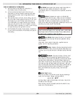
Page 17: ...sition Turn thermostat or controller down again and check damper position indicator returns to closed position Vent Damper Manual Operation Vent damper may be placed in open position to permit burner operation by using HOLD DAMPER OPEN switch located on damper controller Thermostat will control burner firing as before while damper will remain open DO NOT turn damper open manually or motor damage w...

Page 18: ... regulation should be used by propane installer Propane gas piping should be checked out by propane installer CHECKING GAS PIPING DANGER Fire Hazard Do not use matches candles open flames or other methods providing ignition source Failure to comply will result in death or serious injury Pressure test boiler and gas connection before placing boiler in operation Pressure test over 1 2 psig 3 5 kPa D...

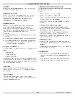
Page 19: ... affected by drafts hot or cold pipes sunlight lighting fixtures televisions a fireplace or a chimney 4 Check thermostat operation by raising and lowering thermostat setting as required to start and stop the burners 5 Instructions for the final adjustment of the thermostat are packaged with the thermostat adjusting heating anticipator calibration etc Set heat anticipator at 2 amps 24 volt thermost...

Page 20: ...12 Integrated High Limit Electronic Ignition Control WARNING Modification substitution or elimination of factory equipped supplied or specified components may result in personal injury or loss of life PN 240013087 Rev A 09 30 2020 ...

Page 21: ...up at highest unit in system If your units have automatic vents manual venting is unnecessary but it will speed up the proper filling of your system If your system is closed expansion tank system you may leave it open to refill system automatically as needed Check temperature pressure gauge Note position of hand indicating pressure This should be between 10 and 15 psi Any lowering of this movable ...

Page 22: ...tly and turn clockwise to OFF Do not force WARNING If you do not follow these instructions exactly a fire or explosion may result causing property damage personal injury or loss of life This appliance is equipped with an ignition device which automatically lights burner Do NOT try to light this burner by hand Before operating smell all around appliance area for gas Be sure to smell next to floor b...

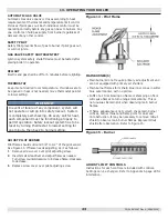
Page 23: ...mostat to lowest setting for one minute then back to normal setting ADJUST PILOT BURNER Pilot flame should surround 3 8 to 1 2 of the pilot sensor See Figure 14 If flame needs adjusting do it as follows 1 Remove screw cover over pilot adjusting screw 2 Insert small screwdriver and adjust flame as needed Turn screw counterclockwise to increase flame clockwise to decrease 3 Replace screw cover over ...

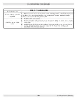
Page 24: ...NING Burn and scald hazard Do not add water until boiler has fully cooled Failure to follow these instructions could result in death or serious injury 3 LWCO Low Water illuminates if boiler is in low water condition Limit control prevents burner operation during this condition Important Have system checked by qualified service agency prior to resuming operation 4 ECONOMY Active Indicates thermal t...

Page 25: ...prioritized If I1 I2 is not used turn Economy Feature OFF House will not get or stay warm 1 Check for air bound radiators 2 Check thermostat settings including heat anticipator settings common on non digital thermostats 3 Check Economy settings Economy feature much like outdoor reset controls lowers average boiler temperature can slow or prevent the house from coming up to temperature Move to lowe...

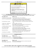
Page 26: ...rol terminals and wire joints Rollout switch blown Have your service agent check heat exchanged for blockage Replace rollout switch with exact replacement Blocked vent blown Have your service agent check venting system and chimney for blockage or down draft condition Reset blocked vent Vent damper not operating Consult troubleshooting guide Possible Cause What to do Gas input amount is incorrect C...

Page 27: ... and piping should be checked at least once a season If vent piping shows any sign of leaking replace immediately WATER SYSTEM If system is to remain out of service during freezing weather always drain it completely water left in to freeze will crack pipes and or boiler CLEANING YOUR BOILER AND BURNERS Flue passages between sections should be examined yearly and cleaned if necessary To clean Remov...

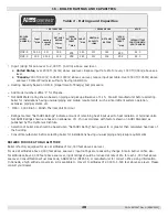
Page 28: ...unusual piping and pickup requirements such as intermittent system operation extensive piping systems etc 3 Mbh 1 000 Btuh British Thermal Unit Per Hour Ratings marked Net AHRI Ratings indicate amount of remaining heat input used to heat radiation or terminal units Net AHRI Ratings shown are based on allowance of 1 15 in accordance with factors shown on AHRI Standard as published by The Hydronics ...

Page 29: ...llow these instructions could result in death or serious injury Control LED legend 1 2 3 4 6 ECONOMY TARGET When the Economy feature is active the Fuel Smart HydroStat continually sets target temperatures below the high limit setting to maximize fuel efficiency When the boiler water reaches the target temperature the LED illuminates and the burner will shut down The boiler water will continue to c...

Page 30: ...it Disconnect ignition cable at SPARK terminal on module WARNING Electrical shock hazard Ignition circuit generates over 10 000 volts Turn OFF electrical power supply at service panel before making electrical connections Failure to do so could result in death or serious injury Energize module and listen for audible sparking noise When operating normally there should be buzzing noise turns on and o...

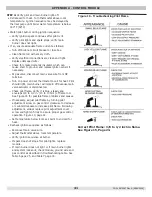
Page 31: ... because main valve actuator is disconnected Check pilot flame Verify it is blue steady and envelops 3 8 to 1 2 in 10 to 13 mm of flame rod See Figure 16 for possible flame problems and causes If necessary adjust pilot flame by turning pilot adjustment screw on gas control clockwise to decrease or counterclockwise to increase pilot flame Following adjustment always replace pilot adjustment cover s...

Page 32: ...set for AC volts 24 volts should be present i IF NOT source of the problem is not in damper check line voltage and 24 volt supply ii If 24 volts is present across brown and black continue to step iii iii Reconnect thermostat wires and turn up heat setting iv Check voltage across black and orange wires in Molex plug 24 volts AC should be present IF NOT source problem is not the damper If 24 volts i...

Page 33: ...tion NO POWER Between 4 1 1 Off on limit 120VAC 2 Bad transformer 3 Loose or broken connections 4 Blown fuse or circuit breaker 5 Disconnect switch off 6 Harness not plugged into receptacle 1 turn limit on 2 Replace transformer 3 Tighten repair or replace connection 4 Replace fuse or reset circuit breaker 5 Turn switch on 6 Plug harness in NO POWER Between 4 2 POWER Between 4 1 When calling for he...

Page 34: ...he obstruction 2 Restore to damper pipe to round verify not binding 3 Correct the condition Damper Rotates Continuously 1 Defective damper motor assembly 1 Replace damper motor assembly Note For troubleshooting only Verify damper is in open position Use service switch to keep damper in open position Place jumper between 2 3 If appliance fires remove jumper and plug receptacle back into damper cont...

Page 35: ...35 Company Address Phone Company Name Tech Initials Service Performed Date PN 240013087 Rev A 09 30 2020 ...

Page 36: ...S OVERRIDE MUST NOT BE USED UNLESS AT LEAST ONE OF THE FOLLOWING CONDITIONS IS TRUE An external energy management system is installed that reduces the boiler water temperature as the heating load decreases This boiler is not used for any space heating This boiler is part of a modular or multiple boiler system having a total input of 300 000 BTU hr or greater This boiler is equipped with a tankless...

Reviews: