background image

28 / 56 


P/N 1070341 • REV 2.0 • ISS 22FEB11 

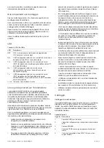
Nota: 

Questo modulo non può essere utilizzato insieme ai 

moduli multiplexati ATS1811/ATS1820. 

ATS1811:

 le schede a otto relè consentono l’uso dei numeri 

uscita da 5 a 48 delle uscite corrispondenti all’indirizzo 
concentratore. Ad esempio, il concentratore 1 usa i relè di 
sblocco 17, 18, 19 e 20 per aprire i varchi, e le uscite da 21 a 
63 sono disponibili attraverso le schede relè. 

ATS1820:


scheda con 16 uscite a collettore aperto. Le uscite 

gestibili attraverso questo modulo sono le stesse gestibili 
mediante ATS1811. 

Il concentratore a 4 varchi può attivare le uscite da 33 a 63 
solo tramite logica macro. 

In caso di utilizzo di più di due moduli ATS1811 o ATS1820, 
usare un’alimentazione separata. 

Impostazione di default delle funzioni dei relè e delle zone 
dell’ATS125x 

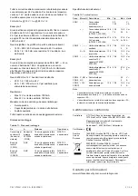
Tabella 7: Valori di default ATS125x 


1 varco  2 varco  3 varco  4 varco

Contatto 

stato 

varco  1 3 5 7 

Zona 

Richiesta 

uscita  2 4 6 8 

DOTL 

9  10 11 12 

Relè 

varco 

K1 K2 K3 K4 


Il numero zona nella Tabella 7 più sopra si riferisce al numero 
zona fisico sul PCB dell’ATS125x. 

I numeri di zona di sistema, corrispondenti a queste funzioni, 
per ciascun ATS125x si trovano nella Tabella 5 a pagina 27. 

Numerazione varchi 

I numeri dei varchi sono determinati da: 

• 

Indirizzo del lettore o della RAS quando questi sono 
collegati sul bus dati di sistema della centrale ATS (varchi 
da 1 a 16). 

• 

Indirizzo del concentratore 4 varchi (varchi da 17 a 64). 

I varchi da 1 a 16, riservati alle RAS da 1 a 16 collegate al bus 
dati di sistema della centrale Advisor Master. Essi consentono 
solo il controllo di base dei varchi (apertura del varco). 

I varchi da 17 a 64 sono utilizzati per i varchi controllati da un 
concentratore ATS125x. Questi varchi consentono funzioni di 
controllo accessi avanzate (anti-passback, ecc.) 

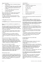
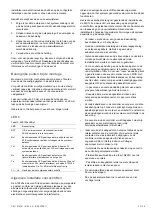
Tabella 8: Numeri varchi assegnati per DGP 

Dispositivo Varco 

RAS da 1 a 16 

Da 1 a 16 (solo apertura varco) 


1 2 3 4 

DGP1  17 18 19 20 

DGP2  21 22 23 24 

DGP3  25 26 27 28 

DGP4  29 30 31 32 

DGP5  33 34 35 36 

DGP6  37 38 39 40 

DGP7  41 42 43 44 

DGP8  45 46 47 48 

DGP9  49 50 51 52 

Dispositivo Varco 

RAS da 1 a 16 

Da 1 a 16 (solo apertura varco) 


1 2 3 4 

DGP10  53 54 55 56 

DGP11  57 58 59 60 

DGP12  61 62 63 64 

Procedura di accensione 

Al termine dell’installazione, assicurarsi che l’unità sia 
indirizzata, come prescritto, mediante gli interruttori da 1 a 4 
del banco di dipswitch. Solo gli indirizzi da 1 a 12 sono 
disponibili

.


Verificare che la memoria RAM nell’ATS125x e nella centrale 
Advisor Master sia la stessa. 

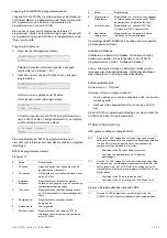
All’accensione iniziale i LED del concentratore 4 varchi 
dovrebbero essere nel seguente stato: 

• RST 

LED: 

OFF. 

LED indicatori bus dati sistema ATS: 

• 

Rx1: Lampeggia quando l’ATS125x riceve i dati di polling 
dalla centrale Advisor Master. 

• 

Tx1: Spento se l’ATS125x non è indirizzato o non è 
programmato per essere interrogato dalla centrale Advisor 
Master. 

LED stato bus dati locale del concentratore 4 varchi: 

• 

Tx: Lampeggia quando l’ATS125x esegue l’interrogazione 
dei dispositivi remoti (lettori/interfacce) sul bus dati locale; 
TX dovrebbe essere sempre attivo. 

• 

Rx: Il lampeggio indica che apparati remoti stanno 
replicando all’interrogazione. 

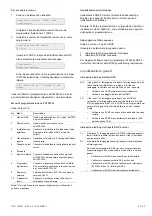
Procedura per l’impostazione 

La minima configurazione consiste nei settagli richiesti per 
l’attivazione il DGP e la connessione delle RAS per la 
programmazione. 

1.  Impostare gli indirizzi per le RAS (lettori o tastiere) 

connesse al bus locale del DGP 4-Varchi. 

2.  Nella centrale Advisor Master, programmazione 

installatore (menu19.4): DGP, attivare l’interrogazione per 
il DGP 4-Varchi e impostare il tipo di DGP. 

Come accedere al menù di programmazione varchi 

L’accesso al menù di programmazione dei varchi avviene 
tramite il menù di programmazione dell’Advisor Master numero 
28, “A dispositivi remoti”. Quando si programma nella sezione 
di programmazione dei 4 varchi si programma direttamente nel 
concentratore (DGP) ATS125x. 

Se non viene concesso l’accesso al menù “A dispositivi 
remoti”, uno o più dei precedenti parametri hardware o di 
programmazione non sono soddisfatti. 

Summary of Contents for Interlogix ATS125 Series

Page 1: ... 2011 Interlogix a UTC Fire Security Company All rights reserved 1 56 P N 1070341 REV 2 0 ISS 22FEB11 ATS125x Four Door DGP Installation Sheet EN FR IT NL PL SV 1 ...

Page 2: ...2 56 P N 1070341 REV 2 0 ISS 22FEB11 2 3 ATS1116 ATS125x ATS CP 1 1 5 6 4 4 4 4 4 2 2 2 3 3 3 3 3 3 7 7 7 8 8 9 ...

Page 3: ... DGP 8 1 ON SD 2 3 4 1 ON SD 2 3 4 1 ON SD 2 3 4 DGP 9 DGP 10 1 ON SD 2 3 4 DGP 11 1 ON SD 2 3 4 1 ON SD 2 3 4 1 ON SD 2 3 4 1 ON SD 2 3 4 DGP 12 5 PCB ATS125x 12V 0V D D 12V 0V D D ATS1170 ATS1190 D D 0V 12V D D 0V 12V 12V 0V D D 6 1 ON SD 2 3 4 1 ON SD 2 3 4 1 ON SD 2 3 4 1 ON SD 2 3 4 1 2 3 4 8 ATS125x 1 C 2 1 2 7 PCB ATS4000 0V D D 0V D D 0V D D 0V D D PCB ATS125x 9 PCB ATS125x NO C NC NO C NC...

Page 4: ...Cards 2 Request to Exit Options RTE Timezone RTE Times Door Open In RTE Disabled When Armed RTE Reporting Out RTE Disabled When Armed 3 Alarm Control Alarm Group Exit Denied if Area Armed Reader Has No Alarm Control RAS Number Disabled Entry Denied if Area Armed 4 Reader Options Zone Holds Door Unlocked Report Forced Door Door Unlocked Until Door Opens Report DOTL Unlock Timezone Reader LED Option...

Page 5: ...se porte ouverte Dans DDS désactivée si arm é Transmission de DDS Hors DDS désactivée si arm é 3 Contrôle d alarme Groupe d alarme Sortie refusée si groupe armé Lecteur sans contrôle d alarme Numéro de RAS désactivé Entrée refusée si groupe armé 4 Options de lecteur Zone maintient porte déver Transmettre porte forcée Porte déverr jusqu à ouverture Transmettre DOTL Tranche horaire de déverrouillage...

Page 6: ...cita Fascia oraria RTE RdU temporizza apertura varco RTE in entrata disabilitata quando inserita Segnalazione della Richiesta uscita RTE in uscita disabilitata quando inserita 3 Controllo di allarme Gruppi di allarme Uscita negata se l area è inserita Il lettore non ha alcun controllo sull allarme Numero di RAS disattivato Entrata negata se l area è inserita 4 Opzioni lettore La zona mantiene il v...

Page 7: ...ijdzone uitgangsverzoek RTE openingstijden In RTE niet actief bij ingeschakeld gebied Rapportage uitgangsverzoek Uit RTE niet actief bij ingeschakeld gebied 3 Alarmcontrole Alarmgroep Geen UIT als ingeschakeld Lezer heeft geen alarmcontrolefunctie GI nummer uitgeschakeld Geen toegang bij ingeschakeld gebied 4 Lezeropties Uitgang houdt deur ontgrendeld Geforceerde deur rapporteren Deur ontgrendeld ...

Page 8: ...Wyj Czas otwarcia drzwi przyciskiem wyj Blok wewn P Wyj gdy zazbrojony Raportowanie Przyc Wyj Blok zewn P Wyj gdy zazbrojony 3 Sterowanie alarmem Grupa alarmowa Brak wyjścia gdy strefa zazbr Czytnik nie ma kontroli alarmu Numer ZAZ zablokowany Brak wstępu gdy strefa zazbr 4 Opcje czytnika Linia utrzymuje otwarcie drzwi Raport wymuszonego otwarcia Otwarcie drzwi dopóki otwarte Raport DOTL Okno czas...

Page 9: ...k Wire Description CON2 Aux power Aux power S S External siren output CON3 Lock 1 power Lock 2 power CON4 NO COM NC Door 1 relay NO COM NC Door 2 relay CON5 NO COM NC Door 3 relay NO COM NC Door 4 relay CON6 0V D D System databus and panel tamper wiring see ATS system databus connection on page 11 for details T C Tamper switch CON7 1 2 3 4 Zone 1 4 inputs C Common CON8 5 6 7 8 Zone 5 8 inputs C Co...

Page 10: ...aintain a separation between low voltage and mains supply cables Use separate points of cable entry to the control panel cabinet If the upper and or lower cabinet entry cable holes are used to route wiring into the control panel always use a proper pipe fitting system by means of an appropriate conduit and junction box For this purpose use only materials of suitable flammability class HB or better...

Page 11: ... 2 7 Device in metal housing 8 Device in plastic housing 9 ATS control panel ATS system databus connection See Figure 7 The system databus is used to connect DGPs such as ATS125x and arming stations to the ATS control panel Remote devices can be up to 1 5 km from an ATS control panel Each remote device is assigned an address and is polled in sequence by the ATS control panel Up to 12 four door DGP...

Page 12: ...or DGP address and RAS address on local databus See Table 5 above for more details 16 RASs can be connected to each ATS125x local databus The RAS addresses relate to specific doors on the ATS125x and to the reader location if readers are mounted on both sides of the same door Table 6 RAS address and reader function IN IN OUT OUT Door 1 1 5 9 13 Door 2 2 6 10 14 Door 3 3 7 11 15 Door 4 4 8 12 16 Ou...

Page 13: ...d to activate the DGP and the connected RASs for programming 1 Set addresses of RASs readers or keypads connected to the local databus of the four door DGP 2 In the Advisor Master control panel installer programming menu 19 4 DGP activate polling for the four door DGP and set the DGP type How to access the ATS125x programming menu Access to the Door programming menu is via the Advisor Master Insta...

Page 14: ...ATS125x menu 1 4 Poll RAS Check that RASs are addressed correctly Specifications ATS1251 ATS1253 ATS1252 ATS1254 General specifications End of line resistor Default 4 7 kΩ 2 0 25 W Other 10 kΩ 2 0 25 W 2 2 kΩ 2 0 25 W Housing See Table 1 on page 9 PCB 202 x 218 x 48 mm Colour Beige Operating temperature 10 to 55 C Humidity 95 non condensing IP protection grade IP30 Mains power specifications Mains...

Page 15: ...ants to meet Approval grade EN 1 2 with two 18 Ah batteries The application has a maximum load of 24 V Locks of 800 mA According Table 10 above it means that the max available auxiliary current is 1400 mA at 24 V This means that besides the 800 mA for the 24 Locks either 1400 800 600 mA is left at 24 V Aux or 600 x 1 6 960 mA left at 12 V Aux i e AUX power Locale Comms Example 2 One wants to meet ...

Page 16: ...nsions ATS1251 12 VDC 12 VDC ATS1642 grand 480x464x160 mm ATS1252 12 VDC 24 VDC ATS1642 grand 480x464x160 mm ATS1253 12 VDC 12 VDC ATS1640 petit 445x315x90 mm ATS1254 12 VDC 24 VDC ATS1640 petit 445x315x90 mm Utiliser 2 batteries 12 V en série Présentation du DGP à 4 portes ATS125x Figure 1 légende Numéro Description 1 Commutateurs DIP d adressage voir Configuration des commutateurs DIP en page 19...

Page 17: ... le mur latéral N utilisez ces unités que dans un environnement propre et sans humidité Mount the unit using screws or bolts through the four mounting holes in the base Voyants lumineux Tableau 3 LEDs ATS125x LED Description RST Si ce voyant clignote les données scrutées sont reçues de la centrale ATS sur le bus de données du système Rx1 Si ce voyant clignote le DGP à 4 portes répond à la scrutati...

Page 18: ... un module est placé dans un coffret en plastique il est inutile de connecter la borne de terre Mise à la terre de coffrets d un même bâtiment Les équipements d un même bâtiment seront systématiquement raccordés à la terre La terre doit être testée par un électricien qualifié Cas de plusieurs bâtiments Si le câblage s étend à plusieurs bâtiments faites appel à plusieurs systèmes de mise à la terre...

Page 19: ...t sorties sont numérotés en fonction d une formule donnée Ceci est utilisé lors de la détermination de numéros d emplacements physiques de DGP de sorties etc au cours de la programmation Tableau 5 Zones RAS et sorties allouées par DGP DGP centrale Zones RAS sorties DGP centrale Zones RASs sorties Centrale 1 16 DGP 7 113 128 DGP 1 17 32 DGP 8 129 144 DGP 2 33 48 DGP 9 145 160 DGP 3 49 64 DGP 10 161...

Page 20: ... adresse du DGP à 4 portes 17 à 64 Les portes 17 à 64 sont utilisées pour les numéros de porte et sont contrôlées par un DGP à 4 portes ATS125x Ces portes assurent des fonctions de contrôle d accès avancées anti retour par exemple Tableau 8 Numéros de porte et d ascenseur par DGP Module adresse Numéro de porte RAS 1 à 16 1 à 16 ouvre porte uniquement 1 2 3 4 DGP1 17 18 19 20 DGP2 21 22 23 24 DGP3 ...

Page 21: ... le DGP à 4 portes au démarrage initial Ceci est réaliser via menu option 3 Initialiser base de données du menu de programmation Attention Toutes les options de programmation seront remises à leur valeur d usine par défaut Les paramètres usine sont indiqués dans le guide de programmation Scrutation RAS connectés Aller dans le menu 1 Options DGP Définissez ou sélectionnez les options suivantes 1 En...

Page 22: ...entation commutée et bus local Fusibles F1 Batterie 1 5 A rapide 20x5 F2 Sortie d alimentation auxiliaire 1 A rapide 20x5 F3 Bus de données local 1 800 mA rapide 20x5 F4 Bus de données local 2 800 mA rapide 20x5 F5 Lock power 1 2 A rapide 20x5 F6 Lock power 2 2 A rapide 20x5 F7 Switched power 1A rapide 20x5 Secteur Fusible secteur 800 mA lent 20x5 Le fusible secteur se trouve dans le bornier secte...

Page 23: ...on Min Typ Max Unit CON3 Sortie alimentation ventouse modèle 12 V ATS1251 ATS1253 13 6 13 8 14 0 2 VDC A Sortie alimentation ventouse modèle 24 V ATS1252 ATS1254 27 4 27 6 27 8 2 VDC A CON4 CON5 C NO or NC Relais de contacts de porte chacun 30 2 VAC A CON9 CON10 12 V Alimentation du bus local 13 6 13 8 14 0 2 VDC A Notes La consommation maximum totale des sorties d alimentation auxiliaires et la s...

Page 24: ...Ingresso manomissione CON7 1 2 3 4 Zone 1 4 ingressi C Comune CON8 5 6 7 8 Zone 5 8 ingressi C Comune CON9 12V 0V D D Bus dati locale per la connessione di RAS e DGP vedere Connessione del bus dati locale dell ATS125x a pagina 26 per dettagli CON10 12V 0V D D Bus dati locale per la connessione di RAS e DGP vedere Connessione del bus dati locale dell ATS125x a pagina 26 per dettagli Per modelli a 2...

Page 25: ... del dispositivo di controllo Se vengono usati i fori nella parte superiore o inferiore dell armadio metallico per il passaggio dei cavi usare sempre tubi di raccordo scatole di giunzione ed accessori appropriati Usare materiale resistente al fuoco Classe HB o superiore Per il collegamento alla rete elettrica collegare i cavi ai morsetti di alimentazione di rete predisposti o tramite una connessio...

Page 26: ...ssere connesso su uno solo dei lati di ciascuna sezione ad un unico punto di messa a terra comune vedi figura sotto Se il cavo dati del sistema viene fatto transitare da più di un contenitore in plastica è necessario connettere tra loro gli schermi del cavo in arrivo e in partenza Legenda Figura 3 Oggetto Descrizione 1 Alimentazione con connessione locale 2 Connettore alimentazione 3 Bus dati di s...

Page 27: ...non è disponibile p es DGP1 zone 17 48 DGP2 non disponibile DGP3 zone 49 64 Vedere Impostazione di default delle funzioni dei relè e delle zone dell ATS125x a pagina 28 per maggiori informazioni sulle impostazioni di fabbrica per le zone e relè di sblocco Nota L ATS125x DGP 4 Varchi ha solamente 8 zone a bordo Ulteriori 24 zone possono essere connesse utilizzando i moduli di espansione ATS1202 RAS...

Page 28: ... varco 1 2 3 4 DGP1 17 18 19 20 DGP2 21 22 23 24 DGP3 25 26 27 28 DGP4 29 30 31 32 DGP5 33 34 35 36 DGP6 37 38 39 40 DGP7 41 42 43 44 DGP8 45 46 47 48 DGP9 49 50 51 52 Dispositivo Varco RAS da 1 a 16 Da 1 a 16 solo apertura varco 1 2 3 4 DGP10 53 54 55 56 DGP11 57 58 59 60 DGP12 61 62 63 64 Procedura di accensione Al termine dell installazione assicurarsi che l unità sia indirizzata come prescritt...

Page 29: ...ione del database Inizializzare il DGP 4 Varchi al momento dell accensione Questo viene eseguito tramite il menu varchi opzione 3 Inizializzazione database Cautela Tutta la programmazione e le impostazioni verranno resettate ai valori di fabbrica I valori di fabbrica sono riportati nella guida di programmazione Interrogazione RAS connesse Andare nel menu 1 opzioni DGP Impostare o selezionare le se...

Page 30: ...te della batteria Per la variante 12 V 3900 mA possono essere distribuiti Un valore elevato di corrente porta l alimentatore in limitazione di corrente Per la variante 24 V 1600 mA possono essere distribuiti sui contatti 27 6 V Serratura e Batteria e 1000 mA possono essere distribuiti sui contatti 13 8 V Alimentazione ausiliaria incluso Switched e bus dati locale Fusibili F1 Batteria 1 5 A Fast 20...

Page 31: ...km lunghezza totale bus dati di sistema senza schede di ripetizione WCAT 52 o equivalente Specifiche terminali esterni Tabella 12 Terminali esterni Conn Morsetti Descrizione Min Tip Max Unità CON1 Connessione secondaria trasformatore c a 20 120 V VA Connessione batteria 12 V variante ATS1251 ATS1253 13 6 13 8 7 2 14 0 25 V A Connessione batteria 24 V variante ATS1252 ATS1254 27 4 27 6 2 x 7 2 27 8...

Page 32: ...nal block Wire Description CON1 Aansluiting van de transformator Systeem aarde zie voor details Aarding op pagina 34 2 x 12V accu s 7 2 Ah 24V variant 1 x 12V accu 7 2 Ah 12V variant CON2 Hulpvoeding S S Externe sirene uitgang CON3 Voeding 1 voor sloten Voeding 2 voor sloten CON4 NO COM NC Deurrelais 1 NO COM NC Deurrelais 2 CON5 NO COM NC Deurrelais 3 NO COM NC Deurrelais 4 CON6 0V D D Aansluitin...

Page 33: ...ingsinvloeden zoals electrische en electromagnetische interferentie Indien de navolgende voorschriften nauwkeurig worden opgevolgd zal het systeem gedurende vele jaren betrouwbaar functioneren Het is van essentieel belang om gedurende de installatie van de ATS125x 4 deuren DI als aanvulling op de volgende voorschriften de geldende locale voorschriften te hanteren die van toepassing zijn op uw inst...

Page 34: ...ouwen Als de bekabeling zich over meerdere gebouwen uitstrekt dient er meer dan één veiligheidsaardingssysteem te worden gebruikt Gebruik ATS1740 isolators repeaters om de systeem databus te isoleren Op deze wijze is het systeem beschermd tegen variaties in aardpotentialen Afscherming De afscherming van alle bekabeling binnen het systeem mag uitsluitend aan één kant op een gemeenschappelijk aardin...

Page 35: ...angen GI s uitgangen Controlepaneel 1 16 DI 7 113 128 DI 1 17 32 DI 8 129 144 DI 2 33 48 DI 9 145 160 DI 3 49 64 DI 10 161 176 DI 4 65 80 DI 11 177 192 DI 5 81 96 DI 12 193 208 DI 6 97 112 Ingangen Aan een ATS125x 4 deuren DI adres zijn standaard 16 ingangen toegewezen of 32 ingangen indien 2 DI adressen worden gebruikt Voor deze ingangen wordt de standaardnummering gebruikt Bijvoorbeeld ATS125x 1...

Page 36: ...ering van deuren Deurnummers worden bepaald door Het GI of lezeradres wanneer aangesloten op de ATS systeem databus deuren 1 16 4 deuren DI adres deuren 17 64 Deur 1 tot en met 16 zijn gereserveerd voor GI 1 tot en met 16 aangesloten op de ATS systeem databus Hiermee is alleen basis toegangscontrole functionaliteit openen van de deur mogelijk De deuren 17 tot en met 64 worden gebruikt als zijnde d...

Page 37: ...enu Beschrijving 8 Programmeer Macrologica Mogelijkheid voor activeren van uitgangen en interne gebeurtenissen door ATS125x gebeurtenissen en logische functies 9 Versienummers Mogelijkheid voor bekijken ATS125x firmware en CPLD versienummer 10 Naar lokale remote units Mogelijkheid voor toegang tot externe interfaces op de lokale databus Opmerking KAARTFORMAAT kan alleen worden ingesteld via manage...

Page 38: ... De benodigde accu capaciteit is gerelateerd aan de keuringsklasse Zie Beschikbare uitgangsstroom en accu capaciteit hieronder om vast te stellen welke stroomwaarde gereserveerd moet worden voor het laden van de accu s Opgemerkt dat het beschikbaar stroomverbruik voor de hulpvoeding voeding voor sloten en voeding lokale databus is beperkt door het accu stroomverbruik Voor de 12 V variant kan 3900 ...

Page 39: ...panningen Alle gegevens zijn gebaseerd op een print zonder externe componenten Afstand bekabeling Tabel 11 Afstand bekabeling Van Naar Afstand Kabeltype Systeem databus ATS controlepaneel J10 ATS125x systeem databus CON6 1 5 km totale databus lengte zonder repeaters WCAT 52 of gelijkwaardig Van Naar Afstand Kabeltype Lokale databus 1 CON9 DI GI 1 5 km totale databus lengte zonder repeaters WCAT 52...

Page 40: ... To złącze jest przeznaczone do tworzenia zakończenia lokalnej magistrali złącze 1 na CON9 15 TERM 3 To złącze jest przeznaczone do tworzenia zakończenia lokalnej magistrali złącze 2 na CON10 Element Opis 16 Złącze do podłączenia rozszerzenia wejść CON14 17 Złącze do podłączenia rozszerzenia wyjść CON15 18 Podłączenie zasilania sieciowego Połączenia Tabela 2 Połączenia ATS125x Złącze Kabel Opis CO...

Page 41: ...iesione jednostki czytniki interfejsy odpowiadają na odpytywanie Dioda Opis Tx Błyskająca dioda LED wskazuje że 4 drzwiowy MZD odpytuje wyniesione jednostki czytniki interfejsy podłączone do lokalnej magistrali ATS125x Dioda LED Tx1 powinna być zawsze aktywna L1 L4 Wskazuje że przekaźnik otwarcia drzwi jest aktywny Ogólne zalecenia odnośnie instalacji Modułu ATS125x zostały zaprojektowane wyproduk...

Page 42: ...enie OSTRZEŻENIE Należy przestrzegać poprawnej procedury uziemiania Uziemianie obudowy zawierającej kilka urządzeń Wszystkie urządzenia zaprojektowane do pracy w systemie mają połączenia uziemiające za pomocą metalowych kołków do metalowej obudowy Należy zwrócić uwagę aby te metalowe kołki miały dobry kontakt z obudową należy wystrzegać się farby Połączenia uziemienia w każdym elemencie sprzętu mo...

Page 43: ... D Zielony Podłączenie styku drzwi i przycisku żądania wyjścia Elementy rysunku 8 Element Opis 1 Styk drzwi 2 Przycisk żądania wyjścia Podłączenie zamka drzwi Patrz rysunek 9 Ustawienia przełączników DIP Przełączniki DIP od 1 do 4 adres MZD są używane do identyfikacji tego modułu MZD wobec centrali Advisor Master tzn do przydzielenia adresu MZD 4 drzwiowe MZD mogą być adresowane tylko jako MZD od ...

Page 44: ...Kiedy używane są więcej niż dwie karty ATS1811 lub ATS1820 należy korzystać z oddzielnych źródeł zasilania Domyślne ustawienia linii i przekaźników modułów ATS125x Tabela 7 Domyślne ustawienia modułu ATS125x Drzwi 1 Drzwi 2 Drzwi 3 Drzwi 4 Styk drzwi 1 3 5 7 Linia żądania wyjścia 2 4 6 8 Linia DOTL 9 10 11 12 Drzwi 1 Drzwi 2 Drzwi 3 Drzwi 4 Przekaźnik drzwi K1 K2 K3 K4 Numery linii w tabeli odpowi...

Page 45: ...nu programowania Dalej Przejdź Menu Menu programowania modułów ATS125x Menu Opis 1 Opcje MZD Opcje globalne dotyczące wszystkich drzwi wind wybranego 4 drzwiowego MZD ATS125x 2 Opcje drzwi Opcje dotyczące poszczególnych drzwi lub wind modułów ATS125x 3 Inicjowanie bazy danych Umożliwia inicjowanie bazy danych drzwi lub wind Powoduje zresetowanie wszystkich danych w module MZD do ustawień domyślnyc...

Page 46: ... 2 V ATS1251 ATS1253 ATS1252 ATS1254 Wydajność prądowa zasilacza 4 0 A maks at 13 8 0 2 V 1 6 A maks at 27 6 V 1 1 A maks at 13 8 V Pomocnicze wyjście zasilacza 13 8 0 2 V 2 A maks Uwaga Maksymalny stały prąd zasilania urządzeń wyniesionych w warunkach braku alarmów Wyjście baterii akumulatorowej 13 8 0 2 V 27 6 0 2 V Typ baterii akumulatorowej Żelowe bezobsługowe Pojemność baterii ATS1251 1 x 26 ...

Page 47: ...ykożystać 1400 800 600 mA na wyjściu pomocniczym 24 V Aux oraz 600 x 1 6 960 mA na wyjściu pomocniczym 12 V czyli wyjściu zasilania urządzeń wyniesionych Przykład 2 Wymagana jest zgodność z NF A2P 2 systemu z dwiema bateriami 18 Ah Obciążenie 200 mA stanowi zasilanie 12 V urządzeń wyniesionych Zgodnie z Tabelą 10 oznacza to że maksymalny prąd pomocniczy wynosi 400 mA przy 24 V Ten prąd 200 mA przy...

Page 48: ...160 mm ATS1253 12 V 12 V ATS1640 liten 445x315x90 mm ATS1254 12 V 24 V ATS1640 liten 445x315x90 mm För 24 V modeller använd alltid två seriekopplade batterier ATS125x dörrundercentral överblick Bilden nedan visar de fyra olika modellerna av dörrcentralerna Figur 1 förklaring Artikel Beskrivning 1 DIP switchar se DIP switchinställningar på sidan 50 2 RAM eller IUM valbart 3 EPROM fabriksmonterat Ar...

Page 49: ...när det gäller miljöelektriska och elektromagnetiska störningar i enlighet med gällande relevanta standarder Om följande riktlinjer följs kommer systemet att ge många års tillförlitlig drift Förutom följande riktlinjer under installationen av ATS125x dörrcentral är det viktigt att följa alla länders lokala krav på installation samt lokalt tillämpliga standarder Endast en behörig elektriker eller a...

Page 50: ...het i metallkapsling 8 Enhet i plastkappsling 9 ATS centralapparat ATS systemdatabuss anslutning Se Figur 7 Systemets databuss används till att ansluta DGP er som ATS125x och RAS ar manöverenheter till Advisor Master centralapparat Dessa enheter kan anslutas upp till 1 5 km från centralapparaten Varje enhet har en egen adress och pollas i serie av centralapparaten Upp till 12 dörrcentraler kan ans...

Page 51: ...ia den lokala databussen Adressen för RAS anger vilken dörr den kommer att styra på ATS125x samt om den är tänkt att vara in eller utläsare Tabell 6 RAS adressering och läsarfunktion IN IN UT UT Dörr 1 1 5 9 13 Dörr 2 2 6 10 14 Dörr 3 3 7 11 15 Dörr 4 4 8 12 16 Utgångar Dörrcentralen har en utgång för extern siren Det finns även fyra utgångar för lås en för varje dörr K1 till K4 DGP n kan adresser...

Page 52: ...l den lokala databussen på dörrcentralen 2 I programmeringsmenyn på Advisor Master menu 19 4 DGP aktivera pollning för dörrcentralen samt ange DGP typ Åtkomst till ATS125x programmeringsmeny Åtkomst till dörrprogrammering via Advisor Master Installationsmenyn 28 Fjärrenheter Vid programmering i denna meny programerar du i verkligheten ATS125x och inte centralen Om du nekas åtkomst till Fjärrenhete...

Page 53: ...53 ATS1252 ATS1254 Kraftspecifikationer Spänning 230 V 10 50 Hz 10 129 VA max Strömåtgång vid 230 V 560 mA max Kretskortets matningsspänning J17 30 VAC typical Powersupply specifikationer Spänning 13 8 0 2 V 27 6 0 2 V Ström 4 0 A max vid 13 8 0 2 V 1 6 A max vid 27 6 V 1 1 A max 13 8 V AUX utgångar 13 8 0 2 V 2 A max Obs Maximalt permanent uttag för att spänningssätta enheter vid inga larm Batter...

Page 54: ...A 24 V Dessa 200 mA 12 V resulterar i 200 1 6 125 mA 24 V vilket lämnar 400 125 275 mA 24 V för AUX t ex låsspänning Restriktioner Max 12 V AUX ström 1000 mA Max 24 V AUX ström 1600 mA Maximal auxiliaryström kan minska beroende på Urladdningstid Batteriladdning AUX säkring Alla data är utan externa anslutningar Kabellängder Tabell 11 Kabellängder Från Till Avstånd Kabeltyp Advisor Master system da...

Page 55: ...r i direktiv 1999 5 EG 2002 96 EC WEEE Produkter märkta med denna symbol får inte kastas i allmänna sophanteringssytem inom den europeiska unionen För korrekt återvinning av utrustningen skall den returneras din lokala återförsäljare vid köp av liknande ny utrustning eller lämnas till en därför avsedd deponering För mer information se www recyclethis info Kontaktinformation www utcfireandsecurity ...

Page 56: ...56 56 P N 1070341 REV 2 0 ISS 22FEB11 ...

Reviews: