background image

P/N 3100973-ML • REV 2.0 • ISS 16MAR11 


3 / 14 

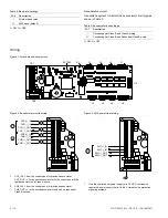
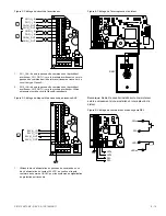
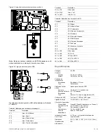
Figure 4: Remote key switch wiring 

RKEY


Note:

 Remove the jumper installed on EXTSW only if you are 

installing a remote key switch. 

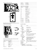
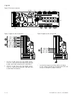
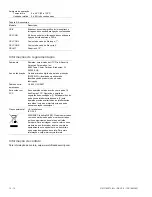
Figure 5: Switch and LED wiring 

LED+
LED+
SW-
SW-

LED+

SW–

+

SWxx

LEDxx


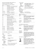
Switch and LED terminals are listed in Table 4 and Table 5. 

Table 4: Switch terminal definitions 

Terminal Description 

J7-1 ACK/Silence 

SW 

J7-2 Reset 

SW 

J7-3 

Signal Silence SW 

J7-4 Drill 

SW 

J7-5 

Lamp Test SW 

J7-6 to J7-8 

Not used 

Terminal Description 

J7-9 to J7-12 

SW 1 to SW 4 

J8-1 to J8-12 

SW 5 to SW 16 

Table 5: LED terminal definitions 

Terminal Description 

J1-1 Reset 

LED 

J1-2 

Signal Silence LED 

J1-3 Drill 

LED 

J1-4 

Ground Fault LED 

J1-5 Trouble 

LED 

J1-6 Controls 

Enable 

LED 

J1-7 ACK/Silence 

LED 

J1-8 

Lamp Test LED 

J2-1 Power 

LED 

J2-2 

Fire Alarm LED 

J2-3 Supervisory 

LED 

J2-4 to J2-8 

Not used 

J3-1 to J3-8 

LED 1 to LED 8 

J4-1 to J4-8 

LED 9 to LED 16 

J5-1 to J5-8 

LED 17 to LED 24 

J6-1 to J6-8 

LED 25 to LED 32 

Specifications 

 
Voltage 24 

VDC 

Current 
 Standby 
 Alarm 

 
36 mA at 24 VDC 
146 mA at 24 VDC 

Switch inputs 
 Quantity 
 Type 

 
5 dedicated, 21 total 
Dry contact 

Open collector outputs
 Current 
 Power 

factor 

 Quantity 
 Type 

For LED driver use only 
10 mA at 5.7 V input max. 
PF 1.0 (resistive) 
43 
Common (11), zone or programmable (32) 

LED current 

7 mA at 5.7 VDC per LED, typical 

Power wiring 

14 to 18 AWG (1.0 to 2.5 mm²) 

Annunciator circuit 
 Class/Style 
 Wire 

size 

 Type 
 Length 
 Baud 

rate 

 
Class B, Redundant Class B, or Class A 
18 to 14 AWG (1.0 to 2.5 mm²) 
Twisted pair, 6 twists per ft. min. 
4,000 ft. (1,219 m), max. 
9600 to 115200 baud 

Remote key switch 

5 VDC at 1 mA, power-limited, unsupervised 

Dimensions  

3.25 × 10.25 × 1.50in. (8.3 × 2.6 × 3.8 cm) 

Ground fault 
impedance 


Operating environment
 Temperature 
 Relative 

humidity 

 
32 to 120°F (0 to 49°C) 
0 to 93% noncondensing 

Summary of Contents for EDWARDS GCI

Page 1: ...ewing the mounting track to the backbox It is not necessary to remove the GCI card 2 Set DIP switch S1 as required See DIP switch settings for details 3 Connect the field wires switches and LEDs as required See Wiring on page 2 for details 4 If you are connecting a remote key switch remove the jumper from the EXT SW pins and attach the remote key switch connector to the pins DIP switch settings Th...

Page 2: ...8 J7 1 12 J4 1 8 J8 1 12 J5 1 8 J6 1 8 TB1 TB2 J15 EXTSW S1 Figure 2 Annunciator circuit wiring 1 2 CH1 _IN CH1 _IN CH1 _OUT CH1 _OUT CH2 _IN CH2 _IN CH2 _OUT CH2 _OUT 1 CH1_IN from the control panel or previous annunciator CH1_OUT to the next annunciator or to the control panel if the last annunciator on a Class A circuit 2 CH2_IN from the control panel or previous annunciator CH2_OUT to the next...

Page 3: ...D J2 3 Supervisory LED J2 4 to J2 8 Not used J3 1 to J3 8 LED 1 to LED 8 J4 1 to J4 8 LED 9 to LED 16 J5 1 to J5 8 LED 17 to LED 24 J6 1 to J6 8 LED 25 to LED 32 Specifications Voltage 24 VDC Current Standby Alarm 36 mA at 24 VDC 146 mA at 24 VDC Switch inputs Quantity Type 5 dedicated 21 total Dry contact Open collector outputs Current Power factor Quantity Type For LED driver use only 10 mA at 5...

Page 4: ...adores programables 11 salidas de indicadores LED dedicados para alimentación controles comunes estado del sistema indicadores de controles de habilitación Treinta y dos salidas de indicadores LED para los indicadores de zona o estado de dispositivos Un zumbido que genera un sonido cuando el panel de control activa un evento La tarjeta GCI no proporciona aislamiento contra falla de conexión a tier...

Page 5: ...e A O El circuito tiene capacidad para cableado Clase B y Clase B redundante I ON O OFF Cableado Figura 1 Terminales y conectores J1 1 8 J2 1 8 J3 1 8 J7 1 12 J4 1 8 J8 1 12 J5 1 8 J6 1 8 TB1 TB2 J15 EXTSW S1 Figura 2 Cableado del circuito del anunciador 1 2 CH1 _IN CH1 _IN CH1 _OUT CH1 _OUT CH2 _IN CH2 _IN CH2 _OUT CH2 _OUT 1 CH1_IN desde el panel de control o el anunciador anterior CH1_OUT hasta...

Page 6: ...confirmación silencio J1 8 LED de Prueba de luces J2 1 LED de encendido J2 2 LED de alarma contra incendio J2 3 LED de supervisión J2 4 a J2 8 No se utiliza J3 1 a J3 8 LED 1 a LED 8 J4 1 a J4 8 LED 9 a LED 16 J5 1 a J5 8 LED 17 a LED 24 J6 1 a J6 8 LED 25 a LED 32 Especificaciones Voltaje 24 VCC Corriente En espera Alarma 36 mA a 24 VCC 146 mA a 24 VCC Entradas de conmutador Cantidad Tipo 5 dedic...

Page 7: ...ity com FR Fiche d installation Description La GCI Carte Graphique Interface Annonciateur permet de connecter un panneau de commande d alarme incendie PCAI compatible et conforme aux normes UL ULC à un avertisseur graphique doté de voyants DEL La carte GCI comprend Cinq entrées de commutateur dédiées pour des commandes courantes Seize entrées de commutateur programmables Onze sorties DEL dédiées p...

Page 8: ...paramètre doit correspondre au paramètre de débit en bauds du panneau de commande Tableau 2 Paramètres du débit en bauds S1 6 Description I Tous les autres débits en bauds O 9 600 bauds par défaut I ON activé O OFF désactivé Circuit d avertisseur Utilisez le segment 7 du commutateur pour sélectionner le type de circuit de l avertisseur tel qu indiqué dans le Tableau 3 Tableau 3 Paramètres du bus d...

Page 9: ... prochain avertisseur Utilisé uniquement sur des circuits Classe B redondants Figure 3 Câblage du dispositif de hausse de puissance AUX 24V _IN 24V _IN 24V _OUT 24V _OUT 1 1 Utilisez le bloc d alimentation du panneau de commande ou un bloc d alimentation de courant 24 VCC en continu et régulé conforme aux normes UL ULC pour les systèmes de signalisation de protection anti incendie Figure 4 Câblage...

Page 10: ... 5 mm Paire torsadée 6 torsades par pied min 1 219 m 4 000 pieds max 9 600 à 115 200 bauds Interrupteur à clé distant 5 VCC à 1 mA limité en puissance non parcouru par un courant permanent Dimensions 8 3 x 2 6 x 3 8 cm 3 25 x 10 25 x 1 5 po Impédance de défaut de mise à la terre 0 Ω Environnement de fonctionnement Température Humidité relative 0 à 49 C 32 à 120 F 0 à 93 sans condensation Tableau 6...

Page 11: ...iver conectando um interruptor remoto com chave remova o jumper dos pinos EXT SW e prenda o conector do interruptor remoto com chave aos pinos Configurações da chave DIP O cartão GCI oferece uma chave DIP de 8 segmentos para configurar o endereço do cartão a taxa de transmissão e o tipo de circuito anunciador ao qual ele está conectado Nota O segmento 8 da chave não é utilizado Endereço do cartão ...

Page 12: ...unciador anterior CH1_OUT para o próximo anunciador ou para o painel de controle se for o último anunciador num circuito Classe A 2 CH2_IN do painel de controle ou do anunciador anterior CH2_OUT para o próximo anunciador Usado apenas em circuitos Classe B redundantes Figura 8 Ligação do riser de força AUX 24V _IN 24V _IN 24V _OUT 24V _OUT 1 1 Use a fonte de energia do painel de controle ou um font...

Page 13: ... ACK Silêncio J1 8 LED Teste de Lâmpadas J2 1 LED de Força J2 2 LED Alarme de Incêndio J2 3 LED Supervisão J2 4 a J2 8 Não usado J3 1 a J3 8 LED 1 a 8 J4 1 a J4 8 LED 9 a LED 16 J5 1 a J5 8 LED 17 a LED 24 J6 1 a J6 8 LED 25 a LED 32 Especificações Voltagem 24 VDC Corrente Standby Alarme 36 mA em 24 VDC 146 mA em 24 VDC Entradas de interruptores Quantidade Tipo 5 dedicados 21 total Contato seco Sa...

Page 14: ... localizada na etiqueta de identificação do produto são o ano de fabricação Padrões norte americanos UL 864 ULC S527 Em acordo com FCC Esse aparelho está de acordo com a parte 15 das Regras FCC Operação é sujeita às seguintes duas condições 1 Este aparelho não pode causa interferência danosa e 2 este aparelho precisa aceitar todas as interferências recebidas inclusive a interferência que pode caus...

Reviews: