


6 / 8
P/N 1061018 • REV E • ISS 14JUL11
8. Strip 3/8 in. of insulation from each wire.
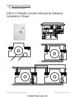
9. Determine the correct wiring, and then insert the wires
under the appropriate screw terminals. See "Wiring" and
Figure 4 to Figure 6.
10. Tighten both screws to secure the base to the wall plate.
11. Replace the detector cover.
12. Apply power. The LED should flash green for
approximately four seconds, and then pulse green.
13. If required by the AHJ or local codes, affix the supplied CO
Warning Label (P/N 10634757) in proximity to the
detector.
14. Test in accordance with “Testing” below.
Wiring
There are three typical wiring configurations:
•
Single device and single zone (Figure 4)
•
Multiple devices in a single zone (Figure 5)
•
Multiple devices with separate alarm and trouble zones
(Figure 6)
Notification
Notification of carbon monoxide detectors should be consistent
with NFPA 720 and the local AHJ. Notification zones should be
consistent with the emergency plan for the protected premises.
Maintenance
Note:
The 250-CO is shipped from the factory as an
assembled unit; it contains no user-serviceable parts and
should not be disassembled.
Clean the outside of the detector each month with a clean cloth
(either dry or dampened with water) to keep openings free from
dust and dirt.
Do not paint the detector or expose it to cleaning solutions.
CO detector replacement
The 250-CO SafeAir Carbon Monoxide Detector has a long-life
carbon monoxide electrochemical sensor. Replace the detector
with a new 250-CO detector after six years from the date of
manufacture (found on the product label on the back of the
detector) or when the control panel goes into trouble and an
audible/visible annunciation occurs signaling “end of life”.
Testing
WARNING:
To reduce the risk of carbon monoxide poisoning,
test alarm operation when not in use for 10 days or more.
Test the detector by pushing the test button after installation
and once a week to verify that it is functioning properly. If the
detector fails the test, verify all connections, wait briefly then try
again. If the detector fails again, replace it.
Notify all persons and facilities that receive alarm and trouble
signals before beginning the test (to prevent unnecessary
response).
To test the trouble relay:
1. Momentarily
disconnect
the power supply from the
detector and verify that the common trouble relay opens.
2. Verify that the panel reacts correctly to the relay activation.
Test/hush button:
(Refer to Figure 7.) Use the test/hush
button to test the detector and silence an activated detector.
When in alarm, momentarily pushing the test/hush button
silences the integral sounder for five minutes. The red alarm
light stays on, and if CO is still present after five minutes, the
detector once again sounds in the temporal-four pattern. The
detector automatically resets when CO is no longer detected.
Three different tests can be performed by pressing the
test/hush button. How long the button is pressed determines
which tests are performed. See Table 2.
Table 2: Press duration and resulting test
Duration Test
Description
Short press
Buzzer test only
Generates the temporal-four
pattern twice.
Two seconds Buzzer test
Fast CO test
Generates the temporal-four
pattern twice.
While in the fast CO test mode, a
functional carbon monoxide gas
test can be performed using a can
of CO testing agent [1].
Five seconds Buzzer test
Fast CO test
Alarm relay test
Generates the temporal-four
pattern twice.
While in the fast CO test mode, a
functional carbon monoxide gas
test can be performed using a can
of CO testing agent [1].
Activates the alarm relay.
[1] Use the UL-certified “Solo C6” canned CO product from SDi
To test the buzzer:
1. Momentarily
press
the test/hush button.
The sounder generates four quick beeps, followed by five
seconds of silence, and then four quick beeps.
firealarmresources.com


