background image

4

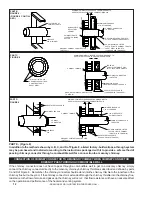
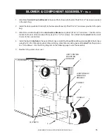
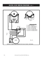
•DRAWINGS FOR ILLUSTRATION PURPOSES ONLY•

Read these rules and the instructions carefully. Failure to follow them will cause a hazard that could result in
death, serious bodily injury, and/or property damage.

Check your local codes. This installation must comply with their rulings.

Do not install this furnace in a mobile home or trailer.

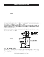
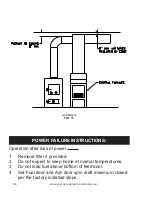
Always connect this furnace to a chimney and vent to the outside. Never vent to another room or inside
a building.

Do not connect this furnace to an aluminum Type B gas vent. This is not safe and is prohibited by the
National Fire Protection Association Code. This furnace requires a masonry or listed factory built
chimney for residential type or building heating appliance chimney. Use a 6" diameter chimney or
larger, that is high enough to give a good draft. (See Page 8)

Be sure that if a masonry chimney is used, it is safely constructed and in good repair. Have the
chimney inspected by the Fire Department or an inspector.

Inspect chimney connector and chimney before and frequently during the heating season for any
deposit of creosote or soot which must be removed (see Chimney Maintenance, page 18.)

Provide air for combustion into the room where the furnace is located. If the intake is not in the same
room, air must have free access to the room.

CAST IRON PARTS MUST BE "SEASONED" TO AVOID CRACKING. BUILD ONLY SMALL FIRES
ON FIRST USE.

To prevent injury, do not allow anyone to use this furnace who is unfamiliar with the correct operation of
the furnace.

For further information on using your furnace safely, obtain a copy of the National Fire Protection
Association (NFPA) publication "Chimney's, Fireplaces and Solid Fuel Burning Appliances" NFPA 211.
The address of the NFPA is Batterymarch Park, Quincy, MA 02269.  For more information on Canadian
installation , obtain a copy of CAN/CSA-B366-M91 Installation Code for Solid Fuel Burning Appliances
and Equipment.

Keep the ashpit section free of excess ashes. Do not allow ashes to stack higher than the sides of the
ash pan.

DISPOSAL OF ASHES - Place ashes in a metal container with a tight fitting lid. Keep the closed
container on a noncombustible floor or on the ground, well away from all combustible materials. Keep
the ashes in the closed container until all cinders have thoroughly cooled. The ashes may be buried in
the ground or picked up by a refuse collector.

CAUTION - The special paints used on your furnace may give off some smoke while they are curing
during the first few fires. Build small fires at first. The metal used in construction of the furnace and
duct work has a light coating of oil. This could give off smoke and/or odors from registers when furnace
is used for the first time. This should disappear after a short period of time. Once this burn-off has
occurred, it should not reoccur.

1.

2.

3.

4.

5.

6.

7.

8.

9.

10.

11.

12.

13.

RULES FOR SAFE INSTALLATION AND OPERATION

Summary of Contents for Ashley 22AF

Page 1: ...E OR TRAILER 851533A FOR INSTALLATION AS A CENTRAL FURNACE CERTIFIED UNDER ANSI UL 391 CAN CSA B366 1 M91 C R US Model 22AF OWNER SMANUAL SOLID FUEL WARM AIR FURNACE UNITED STATES STOVE COMPANY 227 Industrial Park Road P O Box 151 South Pittsburg TN 37380 423 837 2100 Keeping North America W Keeping North America W Keeping North America W Keeping North America W Keeping North America Warm Since 18...

Page 2: ... or Existing Masonry Chimney SEE Page 8 Electrical Wiring 6 Draft Regulator 1 2 Conduit ConduitConnectors FurnaceCement ManufacturerRecommends Rutland Black Code 78 or Equivalent Plenum and Duct Work as Required CONGRATULATIONS You ve purchased one of America s Finest Wood and Coal Burning Furnaces By heating with wood and coal you re helping to CONSERVE AMERICA S ENERGY Wood is our Renewable Ener...

Page 3: ...operly installed a house fire may result For your safety follow the in stallation directions Contact local building or fire officials about restrictions and installation in spection requirements in your area SAFETY NOTICE DANGER RISK OF FIRE OR EXPLOSION DO NOT burn garbage gasoline drain oil or other flammable liquids WARNING FIRE HAZARD DO NOT operate with fire draft exceeding 06 inches W C DO N...

Page 4: ... CRACKING BUILD ONLY SMALL FIRES ON FIRST USE To prevent injury do not allow anyone to use this furnace who is unfamiliar with the correct operation of the furnace For further information on using your furnace safely obtain a copy of the National Fire Protection Association NFPA publication Chimney s Fireplaces and Solid Fuel Burning Appliances NFPA 211 The address of the NFPA is Batterymarch Park...

Page 5: ... fired forced air upflow type central furnace or it may be installed as a central furnace CARING FOR PAINTED PARTS This furnace has a painted outside jacket which is durable but it will not stand rough handling or abuse When installing you furnace use care in handling Clean with soap and warm water when furnace is not hot DO NOT use any acids or scouring soap as these wear and dull the finish DISC...

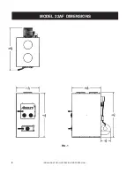
Page 6: ...6 DRAWINGS FOR ILLUSTRATION PURPOSES ONLY MODEL 22AF DIMENSIONS FIG 1 ...

Page 7: ...mm Unit to backwall 30 760 mm Chimney connector pipe to sidewall 18 530 mm Chimney connector pipe to backwall 18 460 mm Hot air ducts to combustibles 2 50 mm NOTE Install only on a noncombustible floor REFER TO FIG 2 3 Place the furnace on a noncombustible floor Check figures 2 and 3 Be sure you have the clearances shown from the furnace and the connector pipe to combustible surfaces If you have a...

Page 8: ...he flue liner to be sure it is safe to use Make repairs before attaching the furnace See Page 4 item 5 Look at Fig 4 The connector pipe and fittings you will need to connect directly to a masonry chimney are shown The chimney connection should be as short as possible If the connector pipe must go through a combustible wall before entering the masonry chimney consult a qualified mason or chimney de...

Page 9: ...tal screws at each chimney pipe joint to make the piping rigid Thechimneyconnectormayincludeasec tionforabarometricdraftregulatorbetween the furnace and the chimney Fig 4 5 6 7 The barometric draft regulator must be installed in the same room same pressure zone as the furnace Installthebarometricdraftregulatorstrictly in accordance with the instructions that are providedwiththebarometricdraftregul...

Page 10: ...himney connector can be connected to a masonry chimney by passing through a combustible wall NFPA Standard 211 allows the following wall pass through systems FIGURE 8 CONNECTION OF CHIMNEY CONNECTOR TO A MA SONRY CHIMNEY THROUGH A COMBUSTIBLE WALL MASONRY CHIMNEY CONSTRUCTED TO NFPA 211 AIRTIGHT CLEANOUT DOOR FLOOR PROTECTOR COMBUSTIBLE WALL TO HEATER CHIMNEY CONNECTOR CEILING SEE PARTS A B C D AN...

Page 11: ...mney connector by means of sheet steel support plates on both ends of the chimney section The opening in the combustible wall shall be covered and the chimney section supported on both sides with sheet steel supports which are at least 24 gauge 0 024 in thickness The sheet steel supports shall be securely fastened to wall surfaces on all sides and shall be sized to fit and hold the chimney section...

Page 12: ...NFPA 211 SHEET STEEL SUPPORTS 24 GAUGE MIN THICKNESS CHIMNEY FLUE MINIMUM CHIMNEY CLEARANCES FROM MASONRY TO SHEET STEEL SUPPORTS AND COMBUSTIBLES 2 IN CONNECTION OF CHIMNEY CONNECTOR TO A MASONRY CHIMNEY WHEN CHIMNEY CONNECTOR DOES NOT PASS THROUGH A COMBUSTIBLE WALL PART E Figure 8 In addition to the methods shown by A B C and D of Figure 8 a listed factory built wall pass through system may be ...

Page 13: ...t using two 2 10 x 1 2 Tek screws Then Mount the bracket to the rear of the furnace with four 4 10 x 1 2 Tek screws Also Attach the Conduit from the Limit Control to the Junction Box 4 Installthefive 5 ClipNutstothebackofthefurnace InstalltheBlower 3 andBlowerGasket 4 tothefurnace using the 1 4 20 x 3 4 bolts provided in the parts bag Attach the remaining piece of Conduit from the junction box to ...

Page 14: ... LOAD LIMIT LINE BREAK OFF JUMPER FOR LOW VOLTAGE FAN OFF INDICATOR FAN ON INDICATOR LIMIT INDICATOR Honeywell LIMIT SWITCH R1 R2 G W 110 VAC 60 HZ GROUND G B W ELECTRICAL JUNCTION BOX M1 M2 BLOWER MOTOR B WIRE NUTS IMPORTANT POWER SUPPLY WIRING MUST NOT BE LESS THAN 90 CENTIGRADE Fig 10 WIRECOLORCODE G GREEN GROUND B BLACK POWER SUPPLY W WHITE POWER SUPPLY R1 WHITE FAN CONTROL R2 BLACK FAN CONTRO...

Page 15: ...ing Furnace as close as practical to the existing central hot air heating system maintainingclearancesasstatedonthelabellocatedon the side of the furnace c Clearances from combustible materials must be complied with as stated on the label below the fuel door Theinstallationmustbemadeonlyonanoncombustible floor d Installthesmokepipeconnectortothechimney with 26 gauge pipe and elbows to be purchased...

Page 16: ...CTIONS Operation after loss of power Remove filter if provided Do not expect to keep home at normal temperatures Do not load fuel above bottom of feed door Set Fuel door and Ash door spin draft maximum closed per the factory installed stops 1 2 3 4 U S ONLY FIG 11 ...

Page 17: ...17 DRAWINGS FOR ILLUSTRATION PURPOSES ONLY CENTRAL INSTALLATION U S CANADA FIGURE 12 ADD ON INSTALLATION U S ONLY FIGURE 13 ...

Page 18: ...COMBINATION CONTROL LIMIT FAN JUMPER IN H H POWER SUPPLY GAS OIL ELECTRIC POWER SUPPLY JUNCTION BOX CENTRAL FURNACE BLOWER MOTOR WOOD FURNACE BLOWER MOTOR CAUTION DO NOT CONNECT PLENUM FAN CONTROL SWITCH ACROSS FURNACE LIMIT CONTROL This unit is certified for parallel installation with exitsting forced air gas or oil fired furnace U S Only ...

Page 19: ...or residential furnaces or any of the specially packed fireplace coals can be used Coalwithalowashcontent 2 to6 isrecommended WOODFUEL Hardwood 18 to26 shouldbesplitandairdried seasoned for 6 months LIGHTING 1 2 3 4 Open the draft controls to HIGH for maximum draft Openthefeeddoorandplacepaperandkindlingonthegrate for starting the fire Light the fire and close the feed door Add wood or about 15 lb...

Page 20: ...of the chimney should be at least 3 feet above the roof and be at least 2 feet higher than any point of the roof within 10 feet Fig 5 See page 28 for list of trouble shooting tips 4 5 6 A DRAFT READING OF 05 TO 06 W C IS SUGGESTED FOR PROPER BURNING OF THIS UNIT WHEN USING WOOD SERVICE HINTS Creosote and Soot Formation and Need for Removal When wood is burned slowly it produces tar and other organ...

Page 21: ...21 DRAWINGS FOR ILLUSTRATION PURPOSES ONLY MODEL 22AF PARTS ...

Page 22: ...uit Assembly 1 24 80131 4 x 4 Junction Box 1 N S 80231 JunctionBoxCover 1 25 68232 Blower Connection Conduit Assembly 1 26 80230 Blower Motor 1 20 hp 1 27 40256 Grate Frame 1 28 40257 Shaker Grate 1 29 40260 Shaker Handle 1 69355 FeedDoorAssembly OrderONLYiftheentireAssemblyisneeded 1 30 25105B Feed Door Painted 1 N S 88066 5 8 Rope Gasket 4 58 ft 31 83872 Door Pin 2 32 89354 Feed Door Handle 1 33...

Page 23: ...23 DRAWINGS FOR ILLUSTRATION PURPOSES ONLY APPENDIX INSTALLATIONA NOTE ANTI BACKDRAFT FLAPPERS OR BAFFLE ARE REQUIRED FOR THIS INSTALLATION ...

Page 24: ...24 DRAWINGS FOR ILLUSTRATION PURPOSES ONLY APPENDIX INSTALLATIONB NOTE ANTI BACKDRAFT FLAPPERS OR BAFFLE ARE REQUIRED FOR THIS INSTALLATION ...

Page 25: ...25 DRAWINGS FOR ILLUSTRATION PURPOSES ONLY APPENDIX INSTALLATIONC NOTE ANTI BACKDRAFT FLAPPERS OR BAFFLE ARE REQUIRED FOR THIS INSTALLATION ...

Page 26: ...26 DRAWINGS FOR ILLUSTRATION PURPOSES ONLY APPENDIX INSTALLATION D U S ONLY INSTALLATION E U S ONLY ...

Page 27: ...27 DRAWINGS FOR ILLUSTRATION PURPOSES ONLY APPENDIX INSTALLATION F INSTALLATION G ...

Page 28: ... a Burning green wood not seasoned or dry b Thermostat setting too low for type fuel a Insufficient draft b Smothering fire when adding fresh fuel a Open spin dampers b Clean chimney c Add raincap to chimney a Allow wood to season in a dry well ventilated area for six months b Set blower control to higher temperature See Page 19 c Set flue draft See Page 9 a Wire unit properly b Replace blower con...

Page 29: ...29 DRAWINGS FOR ILLUSTRATION PURPOSES ONLY NOTES ...

Page 30: ...30 DRAWINGS FOR ILLUSTRATION PURPOSES ONLY NOTES ...

Page 31: ...White Oak 48 4100 9 Fair 28 6 Red Oak 46 3900 8 Fair 27 4 Beech 45 3800 7 Hard 26 8 Sugar Maple 44 3700 6 Fair 26 2 Black Oak 43 3700 6 Fair 25 6 Ash 42 3600 5 Well 25 0 Yellow Birch 40 3400 4 Hard 23 8 Red Maple 38 3200 3 Fair 22 6 Paper Birch 37 3100 3 Easy 22 1 Elm Sycamore 34 2900 2 Very Difficult 20 1 Red Spruce 29 1800 1 Easy 16 1 HEATING WITH WOOD ...

Page 32: ...VE THE FULL MODEL NUMBER WHICH IS ON THE NAMEPLATE ATTACHED TO THE HEATER WHEN ORDERING REPAIR PARTS ALWAYS GIVE THE FOLLOWING INFORMATION AS SHOWN IN THIS LIST 1 THE PART NUMBER 2 THE PART DESCRIPTION 3 THE MODEL NUMBER 22AF 4 THE SERIAL NUMBER ____________________ HOW TO ORDER REPAIR PARTS UNITED STATES STOVE COMPANY 227 INDUSTRIAL PARK ROAD P O BOX 151 SOUTH PITTSBURG TN 37380 423 837 2100 WWW ...

Reviews: