USSC American Harvest 6037 Owner'S Manual Download Page 14

14

USSC

SETTING THE DRAFT

A proper draft setting is crucial to the successful burning of solid fuels.  Draft refers to the amount of air flowing through the

burn chamber of your stove.  Too much or too little draft will cause your stove to burn improperly and may result in the fire

burning out or excessive deposits (clinkers).  Please follow these guidelines carefully as you operate your stove to achieve

maximum efficiency and enjoyment.


The amount of draft required for your stove to burn properly will depend upon your installation and the fuel you use.  You

can set your draft by looking at the flame and following these guidelines.  The manual draft knob is the rod and knob on

the left side of the stove.  Pulling the knob out increases the draft and pushing the knob in decreases the draft.  A little

movement of the knob goes a long way to changing the flame.  It may take several trial and error adjustments on the

draft to achieve the correct setting.
The flame should be an “active” flame.  A flame that moves around lazily and emits visible smoke needs more draft.  To

give the fire more draft, pull the damper out 1/8” and check the flame again.  If the status of the flame has not changed,

move damper another 1/8” until you get a clean “dancing” flame.
The base of the flame should be blue in color and the top of the flame should be yellow.
If the flame does not have enough draft, fuel will build up in the firepot and eventually smother the flame.  If this

happens, or if you notice the firepot is filling up with partially burned fuel, open the damper 1/8” at a time until the fire

is clean and dancing.
If the flame has too much draft, the flame will look like a torch in that it will be moving rapidly and blowing fuel and sparks

out of the firepot.  If you find that you have this condition, move the damper inward 1/8” at a time until the condition of

the flame changes.

MAINTENANCE INSTRUCTIONS

Surfaces on the front of the stove will be extremely hot during operation.  

Always wear heat resistant gloves

to perform periodic maintenance.
Using a wooden stick, tap the side heat exchangers that are located on the left and right sides of the firebox.  When you

open the door, they are located directly inside to the left and right.  When you tap the sides with the wooden stick the

loose fly ash will drop out of these holes.
Pull the lower front ash clean-outs out and scrape any fly ash down into the pedestal ash pan.  Push them back in all the

way.
While you are tapping the side heat exchangers, we recommend that you pull the draft knob all the way out for a minute

or two and put the unit on high fire.  This will allow the unit to self-clean the heat exchanger area, the draft fan and

exhaust chimney pipe.
If clinkers develops in the firepot,clean thoroughly.  You may have to do this once or twice a day depending on the

moisture content of the corn.  If this is not cleaned out, it could cause the fuel stirrer to jam.  Clinkers are a direct result

of excessive corn moisture, or excessive air, and do not indicate a problem with the stove.  USSC highly recommends an

additive (see Additive Pg. 17) be added to your corn to eliminate these clinkers.  Contact your local Feed and Seed for

availability and cost.  You will need this additive if the agitator “fingers” develop an accumulation or build-up.

Daily Maintenance

Soot and Flyash - Formation and Need for Removal

The products of combustion will contain small particles of flyash.  The flyash will collect in the exhaust venting system and

restrict the flow of flue gases.  Incomplete combustion, such as occurs during startup, shutdown, or incorrect operation of

the room heater will lead to some soot formation which will collect in the exhaust venting system.  The exhaust venting

system should be inspected at least once per month (of heavy use) to determine if cleaning is necessary.  Corn has a high

ash content.

DISPOSAL OF ASHES

Disposal of Ashes

Ashes should be placed in a metal container with a tight fitting lid.  The closed container of ashes should be placed on a

noncombustible floor or on the ground, well away from all combustible materials, pending final disposal.  If the ashes are

disposed of by burial in soil or otherwise locally dispersed, they should be retained in the closed container until all cinders

have been thoroughly cooled.

Summary of Contents for American Harvest 6037

Page 1: ... or fire officials about restrictions and installation requirements peculiar to your area Do Not Plug this appliance into an electrical outlet before reading and understanding all operations and always unplug the unit before attempting any work or maintenance Do not connect this stove to any chimney flue already serving another appliance Carefully observe and maintain all clearances and combustibl...

Page 2: ... pellets you re helping CONSERVE AMERICA S ENERGY CONGRATULATIONS Heat Output 53 200 BTU HR Heating Capacity 1 200 Sq Ft Fuel Storage Capacity 60 Lbs Width 28 in 711mm Height 33 in 838mm Depth 28 in 711mm BTU output will vary depending on the brand type and quality of fuel and the moisture content Consult your dealer for best results Based on house construction post 1982 Remember this stove should...

Page 3: ...erican Harvest stove is designed to burn dry shelled corn cherry pits or pelletized fuel such as wood pellets The burning of other solid fuels such as cord wood or wood chips in this stove is not permitted This product requires simple periodic maintenance for proper operation and long life of the stove Read and follow the maintenance schedule closely DISCONNECT THE POWER CORD BEFORE SERVICING THIS...

Page 4: ...midsize kernel corn If the kernel size of the corn varies greatly or if you switch sources frequently you will get a less consistent burn which will require more attention to the draft setting on your stove Therefore purchasing corn from the same source will help achieve a more consistent burn DONOTUSECORNWITHAHIGHWAXCONTENT WOOD PELLETS As with corn be consistent in your pellet supplier Pellets w...

Page 5: ...to Top Edge of Unit 6 in 152mm B Sidewall to Flue 5 in 127mm C Backwall to Flue 3 in 75mm D Backwall to Unit 9 in 228mm E Right Sidewall to Top Edge of Unit 2 in 50mm CORNER F Adjacent Wall to Flue 3 in 75mm G Adjacent Wall to Unit 4 in 100mm BACK WALL SIDE WALL SIDE WALL Backwall Sidewall Parallel BACK WALL Corner Installation NOTE Allow sufficient space to remove the left and right side panels f...

Page 6: ...es not apply if the windows are non opening or have been fixed so they cannot open Distance from bottom of termination and grade 1ft 305mm minimum This is conditional upon the plants and nature of grade surface The exhaust gases are not hot enough to ignite grass plants or shrubs located in the vicinity of the termination The grade surface must not be a lawn Distance from bottom of termination and...

Page 7: ... so could result in a burn back during high winds blowing directly up the air inlet during a simulta neous power failure see diagram above Blockage excessive length or extra bends in the air intake pipe will starve the stove of combustion air A 90 degree bend is equivalent in restriction to approximately 30 inches of straight inlet pipe DESIGN GUIDELINES FOR OUTSIDE COMBUSTION AIR CONNECTION 1 2 3...

Page 8: ...NSTALL IN SLEEPING ROOM 1 Stove must be permanently bolted to the floor Remove the Base Trim and bolt thru the base flange 2 Stove must have permanent outside air source 67FAK 3 Stove must be permanently electrically ground to the steel chassis of the mobile home 4 All vertical chimney vent must have wall supports 5 All exhaust systems must have a spark arrestor CAUTION THE STRUCTURAL INTEGRITY OF...

Page 9: ...nd of the 3 pipe B Alternate Method An approved type PL connector back clamp may be used to allow easy disconnect for mainte nance The RTV sealant must be used in mobile home installation Push stove with pipe attached towards wall Pipe B will go through the wall thimble F Be careful not to dislodge the thimble Position stove not closer than 9 to the wall Install type PL termination cap G with rode...

Page 10: ... 6 Min Non Combustible Hearth Plate Support Bracket 9 Min THROUGH THE WALL VERTICAL PIPE INSTALLATION WITH TERMINATION CAP The Hearth Pad is not required under the unit if the floor is noncombustible but is required 6 inches 152mm beyond the front of the unit and 6 inches 152mm beyond each side of the door NOTE Vertical Pipe must be 4 PL Above 4 ...

Page 11: ...w gasket WARNING Do not operate unit with broken glass Do not substitute original factory glass You must use only factory authorized glass Do not slam door shut Do not strike glass Do not use abrasive cleaners Do not clean when glass is hot CLEANING THE GLASS When the fire is first started it will produce some smoke The smoke might accumulate on the glass surface Before the fire gets hot open the ...

Page 12: ...el Manual Draft Adjustment Slide in or out to adjust the amount of draft flowing through the firebox Service Note For service needed inside the cabinet remove the retaining screws at front and rear CAUTION Use care panel is heavy When removing either panel remove top screw last Remove draft knob and remove panel with care in order to not damage the wiring harness BE SURE that the unit is unplugged...

Page 13: ...the 1 setting the fuel will start to feed into the firepot If the firepot begins to fill up with unburned fuel open the manual draft knob a little to burn up excess fuel If the fire is going out because there is too much fuel coming in turn the heat setting knob off and then turn back on This will give you another 3 minutes before fuel feeds in If the fire is burning too fast and the fuel is being...

Page 14: ... a wooden stick tap the side heat exchangers that are located on the left and right sides of the firebox When you open the door they are located directly inside to the left and right When you tap the sides with the wooden stick the loose fly ash will drop out of these holes Pull the lower front ash clean outs out and scrape any fly ash down into the pedestal ash pan Push them back in all the way W...

Page 15: ...and will remain trouble free Weekly Maintenance SPRING CLEANING When the heating season is over make sure that you clean out all of the fuel in the hopper firebox area ash pan and firepot area Corn and any ash can accumulate moisture over the summer months causing the unit to rust and the fuel to mold It is recommended that prior to shutting down the unit in the spring run the unit on the higher s...

Page 16: ...er Shells and maybe more than a couple handfuls If you notice a heavy accumulation of whitish powder in your burn pot reduce the amount of Oyster Shell Additive Remember using this additive as necessary promotes efficiency higher heat output reduces maintenance clinkers and ash content WARNING These automatic safety features must not be bypassed AUTOMATIC SAFETY FEATURES Power Outage During a powe...

Page 17: ...at ing temperature of 110 degrees is achieved normal operation will con tinue Will continue until shutdown Shutdown will occur when the operating tempera ture is below 90 degrees Will continue intermittingly has deter mined by the HEAT SETTING until shutdown The auger will continue at the feed rate specified by the HEAT SETTING NOTE Safety switches HI limit and vacuum sensor must be activated to c...

Page 18: ... board flashing NOTE HI LIMIT er rors are usually the result of operating at the highest heat setting for long periods of time room fan failure or loose wire connection Continues until the operating tempera ture falls below 90 degrees May take several minutes up to an hour Continues until the operating tempera ture falls below 90 degrees The auger will continue at the lower feed rates until the op...

Page 19: ...ger jams can be a prob lem if poor quality fuel is used Or excessive fines sawdust corn cobs or husk are found in hopper Auger jams are evident when the auger turns but no fuel is delivered Improper air mixture can cause the stove to burn fuel faster than theaugerisfeeding Reducecom bustion air by adjusting air damper or increase feed rate by changing the heat setting CAUSE Auger stops turning Aug...

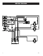
Page 20: ...20 USSC WIRING DIAGRAM ...

Page 21: ...USSC 21 REPAIR PARTS DIAGRAM 6037 45 ...

Page 22: ... 891055 Coupling 1 26 80457 Agitator Motor 1 27 891083 Agitator Sprocket 1 28 891058 Chain 1 29 80455 Auger Safety Switch F250 Thermodisc 60T11 1 30 80381 Low Limit Switch F110 Thermodisc 60T12 1 31 80381 Distribution Blower Limit Switch F110 Thermodisc 60T12 1 N S 80477 Wiring Harness 1 N S 80446 Wire Green 13 Ground 1 32 25170 Gold Trim Bracket 2 33 891073 Gold Trim 1 34 891075 Glass Gasket 1 35...

Page 23: ...USSC 23 Notes ...

Page 24: ...WAYS GIVE THE FULL MODEL NUMBER WHICH IS ON THE NAMEPLATE ATTACHED TO THE HEATER WHEN ORDERING REPAIR PARTS ALWAYS GIVE THE FOLLOWING INFORMATION AS SHOWN IN THIS LIST 1 THE PART NUMBER 2 THE PART DESCRIPTION 3 THE MODEL NUMBER 6037 4 THE SERIAL NUMBER ____________________ HOW TO ORDER REPAIR PARTS United States Stove Company 227 Industrial Park Road P O Box 151 South Pittsburg TN 37380 423 837 21...

Reviews: