USSC
10
NOTE: DIAGRAMS & ILLUSTRATIONS NOT TO SCALE
INFORMATION ON VENTING
ROUTES AND COMPONENTS
Since it is very important that the vent
system maintain its balance between the
combustion air intake and the flue gas
exhaust, certain limitation as to vent
configurations apply and must be strictly
adhered to.
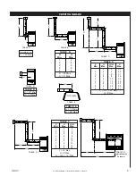
• Max. vertical vent run is 40 ft.
• Max. horizontal vent run is 16 ft.
• A 1/4" rise per foot of horizontal run
must be maintained on all horizontal
runs.
• It is possible to configure a venting
system with 40 feet of vertical vent run
and 16 feet of horizontal vent run and
include up to (3) three elbows.
(See venting tables on page 9.)
IMPORTANT: It is always best to locate
the furnace in such a way that a minimum
of offsets and/or horizontal run is required.
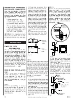
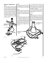
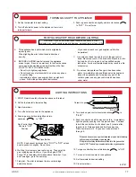
(1) Twist-lock procedure: Four
indentations, located on the female
ends of pipes and fittings, are
designed to slide straight onto the
male ends of adjacent pipes and
fittings, by orienting the four pipe
indentations so they match and slide
into the four entry slots on the male
ends. (Figure 12) Push the pipe
sections completely together, then
twist-lock one section clockwise
approximately one-quarter turn, until
the two sections are fully locked. The
female locking lugs will not be visible
from the outside, on the Black Pipe
or fittings. They may be located by
examining the inside of the female
ends.
(2) Horizontal runs of vent must be
supported every three feet. Wall
Straps are available for this purpose.
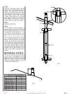
STEP 3:
With the adaptor and pipe attached to the
stove into it's correct location, and mark the
wall for a 11 1/2-inch x 12-inch square hole.
The center of the square hole should line
up with the centerline of the horizontal pipe,
as shown in Figure 13. Cut and frame the
square hole in the exterior wall where the
vent will be terminated. If the wall
being
penetrated is constructed of non-
combustible material, i.e. masonry block or
concrete, a 7-inch diameter
h o l e
is acceptable.
FEMALE
LOCKING
LUGS
MALE
LOCKING
LUGS
Fig. 12
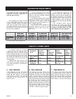
STEP 4:
Position the horizontal vent termination in
the center of the 11 1/2" x 12" hole, and
attach to the exterior wall with the four wood
screws provided. Before attaching the Vent
Termination to the exterior wall, run a bead
of non-hardening mastic around it's outside
edges, so as to make a seal between it and
the wall. The arrow on the vent cap should
be pointing up. Insure that proper
clearances to combustible materials are
maintained. (Figure 14)
(1) The horizontal run of vent must have
a 1/4-inch rise for every 1 foot of run
towards the termination. Never allow the
vent to run downward. This could cause
high temperatures and may present the
possibility of a fire.
(2) The location of the horizontal vent
termination on an exterior wall must meet
all local and national building codes, and
must not be easily blocked or obstructed.
Termination clearances are given on
page 7 & 8.
HOT
WOOD
SCREWS
Fig. 13
NOTE:
(1) The four wood screws provided
should be replaced with appropriate
fasteners for stucco, brick, concrete, or
other types of sidings.
(2) For buildings with vinyl sidings, a
Vinyl Siding Standoff (Part 950), should
be installed between the vent cap and
the exterior wall. (Figure 14). Attach the
Vinyl Siding Standoff to the Horizontal
Vent Termination. The Vinyl Siding
Standoff prevents excessive heat from
possibly melting the vinyl siding material.
VINYL
SIDING
APPLY SEALANT
TO ALL FOUR SIDES
VINYL SIDING
STANDOFF
BOLT HORIZONTAL
TOP TO VINYL
STANDOFF
SCREWS
Fig. 14
PLANNING YOUR
INSTALLATION
When planning your installation, it will be
necessary to select the proper length of
vent pipe for your particular requirements.
To determine the length of vent pipe
required for vertical installations, measure
the distance from the appliance flue outlet
to the ceiling, the ceiling thickness, the
vertical rise in an attic or second story, and
allow for sufficient vent height above the
roofline. For two-story applications,
firestops are required at each floor level. If
an offset is needed in the attic, additional
pipe and elbows will be required.
STEP 2:
Direct Vent pipe and fittings are designed
with special twist-lock connections. To
connect the venting system to the
appliance flue outlet, we have supplied a
twist-lock appliance adaptor built into the
unit at the factory.
STEP 1:
Set the gas appliance in it's desired
location. Check to determine if wall studs
or roof rafters are in the way when the
venting system is attached. If this is the
case, you may want to adjust the location
of the appliance.
HORIZONTAL INSTALLATION
INSTALLATION


