background image

Assembly and Installation

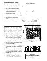
Place the heater on solid masonry or solid concrete. When
the heater is used on a combustible floor, use an Underwrit-
ers Listed floor protector. The floor protector must comply
with UL Standards.  The base should extend at least 18"
beyond the door side of the heater and should extend under
the flue pipe if it is elbowed towards a wall. (Fig. 3).

1.

The stove must have its own flue.  Do not connect this
unit to a chimney flue serving other appliances.

2.

After observing the clearances to combustibles, locate
your floor protector accordingly and carefully place the
stove in your selected location.  Install stove pipe,
elbows and thimble as necessary, utilizing either a
recently cleaned and inspected masonry chimney or a
UL 103 HT Listed Residential Type and Building Heat
ing Appliance Chimney.

3.

If your chimney continues to draft excessively, then use
a Barometric Draft Regulator.

4.

Use three (3) sheet metal screws in each stove pipe and
/or elbow joint to firmly hold the stove pipe together.  Use
6" round black/blue stove pipe, not galvanized stove
pipe .

5.

Recheck illustrations Fig. 1 through 6 to be sure you
have the proper clearances shown from the stove and
the connector pipe to combustible surfaces.  NOTE:  If
a wall is only faced with brick or stone, consider it as a
combustible wall.

6.

DO NOT install this stove in a mobile home or trailer.

7.

If you have too much draft, then install a 6" cast iron
stove pipe damper in the first joint of the stove pipe.

CAUTION!

KEEP FURNISHINGS AND OTHER

COMBUSTIBLE MATERIALS

AWAY FROM THE HEATER.

NON- COMBUSTIBLE
CONSTRUCTION IN
ACCORDANCE WITH
NFPA 211

DASHED LINES
SHOW STRAIGHT
OUT CHIMNEY
CONNECTOR

WRONG

RIGHT

WRONG

FIG. 4

4

38"

54"

36"

36"

FLOOR
PROTECTOR

36"

MINIMUM CLEARANCE

TO COMBUSTIBLE WALLS

1.

Uncrate and/or unpack the heater, remove
cardboard packaging and protective poly
bag.

2.

Attach (4) legs to rail bases to form a base
which stove will set on

3.

Attach boot assembly to rear of stove using
the enclosed hardware package.

4.

Place stove in desired location.

5.

Place top extension on right hand side of the
stove.

6.

Place lid supports into position on top of

stove.

7.

Place lids into position on top of stove.

10-1/4

FLOOR

PROTECTOR

FLOOR

PROTECTOR

11-1/2"

18"

38"

44"

36"

39-1/2"

FIGURE 1

FIGURE 2

HEATER/FLOOR PROTECTOR LOCATION

FIG. 3

Clearances in () are for Canada ONLY.

(48")

(48")

(51-1/2")

(60")

(42")

Summary of Contents for 1864

Page 1: ...O ORDER REPAIR PARTS CORRECTLY KEEP IN A SAFE PLACE FOR FUTURE REFERENCE UNITED STATES STOVE COMPANY 227 Industrial Park Road P O Box 151 South Pittsburg TN 37380 423 837 2100 COMPANY U NITED STATES STOV E C S S U 851500 Owners Manual Owners Manual Owners Manual Owners Manual Owners Manual 1864 1864 1864 1864 1864 Hasty Baker Range Hasty Baker Range Hasty Baker Range Hasty Baker Range Hasty Baker ...

Page 2: ...the center of the hole but it doesn t have to be exact 3 Remove the bracket s 4 Locate and mark the center of the hole with a sharp center punch to prevent the drill from wandering when drilling 5 Use a variable speed drill motor with a 1 4 drill bit Drill the holes at a LOW SPEED setting using light pressure straight through the stove top 6 Complete the assembly of the warming oven as follows Fas...

Page 3: ...ce company may be able to recommend a qualified inspector 6 Creosote or soot may build up in the chimney connector and chimney and can cause a house building fire Inspect the chimney connector and chimney twice monthly during the heating season and clean as necessary See Chimney Maintenance page 6 7 Provide air for proper combustion from outside the house into the room where the stove is located I...

Page 4: ... 5 Recheck illustrations Fig 1 through 6 to be sure you have the proper clearances shown from the stove and the connector pipe to combustible surfaces NOTE If a wall is only faced with brick or stone consider it as a combustible wall 6 DO NOT install this stove in a mobile home or trailer 7 If you have too much draft then install a 6 cast iron stove pipe damper in the first joint of the stove pipe...

Page 5: ...ly listed type HT per UL 103 6 in diameter black or blued chimney connector minimum 24 gauge steel If your chimney starts at the ceiling Fig 6 you will need enough 6 pipe to reach the ceiling The top of the chimney must be at least 3 feet above the roof and be at least 2 feet higher than any point of the roof within 10 feet Fig 6 RULES FOR CONNECTOR PIPE INSTALLATION 5 FLOOR PROTECTOR FIG 5 PIPE B...

Page 6: ...fire department then reduce thefirebyclosingtheinletaircontrolandpouralargequantity of coarse salt baking soda or cool ashes on top of the fire in the firebox CAUTION A chimney fire may cause ignition of wall studs or rafters which you thought were a safe distance from the chimney If you have a chimney fire have your chimney inspected by a qualified person before using again Service Hints Do not e...

Page 7: ...17 891014 Stove Left Side 1 18 891015 Ash Pan Guide 2 19 891016 Left Side Liner 1 20 891017 Stove Bottom 1 21 891018 Side Apron 2 22 891019 Leg 4 23 891020 Front Rear Apron 2 24 891021 Master Handle 1 25 891022 Ash Pan 1 26 891023 Feed Door 1 27 891024 Ash Door 1 28 891025 Door Latch 2 29 891026 Door Handle 2 30 891027 Oven Door 1 31 891028 Oven Door Handle 1 32 891029 Spring Cover 1 33 891030 Doo...

Page 8: ...EN WRITING ALWAYS GIVE THE FULL MODEL NUMBER WHICH IS ON THE NAMEPLATE ATTACHED TO THE BACK OF THE HEATER WHEN ORDERING REPAIR PARTS ALWAYS GIVE THE FOLLOWING INFORMATION AS SHOWN IN THIS LIST 1 The PART NUMBER 2 The PART DESCRIPTION 3 The MODEL NUMBER 1864 4 The SERIAL NUMBER UNITED STATES STOVE COMPANY 227 Industrial Park Road P O Box 151 South Pittsburg TN 37380 423 837 2100 www USSTOVE com ...

Reviews: