background image

SECTION 6-8

APPENDIX

FLOWMAX RO MANUAL REV: B 05/1999

USFilter

United States Filter Corporation

(THIS PAGE INTENSIONALLY LEFT BLANK)

Summary of Contents for FlowMAX FM Series

Page 1: ...rive Lowell MA 01851 USA Tech Support 800 783 7873 Customer Service 800 466 7873 Operation and Maintenance Manual FlowMAX FM Series FS Series Single Pass Reverse Osmosis Unit Model FMX XX Colorado Springs Job XXXXX Rev B Issue Date 05 1999 ...

Page 2: ...LLATION 3 1 Required Tools and Parts 3 1 3 2 Equipment Installation Guidelines 3 2 3 3 Equipment Installation Procedures 3 2 4 0 OPERATION 4 1 Initial Startup 4 1 4 2 Normal Operation 4 3 4 3 Short Term Shutdown Procedure 4 4 4 4 Long Term Shutdown Procedure 4 5 5 0 MAINTENANCE 5 1 Maintenance Schedule 5 1 5 2 Filter Cartridge Replacement 5 1 5 3 Membrane Element Replacement 5 2 5 4 Troubleshootin...

Page 3: ...at the front of the manual The pages within each section are numbered section page with the page numbers starting at 1 and incrementing sequentially NOTE Page numbering will skip over any special documents and continue on the page following the document Special documents will be noted with an introduction statement that is listed in the table of contents Warnings Cautions and Notes are used to att...

Page 4: ...anual discloses information in which USFilter has proprietary rights Neither receipt nor possession of this manual confers or transfers any right to the client and by its retention hereof the client acknowledges that it will not reproduce or cause to be reproduced in whole or in part any such information except by written permission from USFilter The client shall have the right to use and disclose...

Page 5: ...nect the system to piping that has not been approved by USFilter If there are any doubts please call your USFilter local branch 7 Never remove any components from the unit while under pressure 8 No one under the age of 18 years of age should operate or be allowed near this equipment 9 Warning labels have been placed on the equipment to remind the operator of certain hazards Never remove these labe...

Page 6: ...nual should remain with the equipment at all times to act as a ready reference guide for anyone who operates this equipment SAFETY EQUIPMENT Below is a list of equipment and materials that should be kept nearby the equipment The equipment is the bare minimum required to maintain a safe working environment 1 Lock out and Tag out devices for servicing and shutdowns 2 Eyewash safety shower for any ch...

Page 7: ...s of pharmaceutical RO units FlowMAX The FlowMAX RO system is packaged for general industrial applications There are 10 different sizes that come standard with Filmtec BW30 365 membrane elements Codeline FRP 80A side port direct connect pressure vessels There are two standard pump choices the T T horizontal booster pump or the Grundfos BM series submersible pump The standard control package is a A...

Page 8: ...e are the most cost efficient standard 8 RO units available for application where a sophisticated control system is not required These units are available with either Filmtec BW30 365 or BW30 440LE membrane elements and Codeline FRP side port direct connect pressure vessels The standard control package is a C2000 control system The feed piping and product piping is PVC The flow is measured with ro...

Page 9: ...ds in a solution increases the solution s conductivity or the ability to conduct electricity Consequently the use of a conductivity measurement device may be used as a means to approximate the amount of dissolved solids in a solution The higher the conductivity potential of the solution the higher the dissolved solids content Unfortunately the presence of dissolved and suspended solids may be detr...

Page 10: ...ons per square foot of membrane surface per day or in gallons per day per reverse osmosis cartridge The flux rate of a particular membrane is generally limited by several factors including temperature operating pressure and the surface flushing action to keep the membrane surface free of suspended solids The rate of recovery of feed water converted into product water is generally expressed in the ...

Page 11: ...ut of the element The element is then covered with an outer wrap of semi rigid fiberglass for protection and to assist in maintaining a uniform round shape The final dimensions of the element are usually approximately 40 long by either 4 or 8 in diameter The elements are then put into one or more cylindrical pressure vessels which can contain one to six membrane elements depending on the unit desi...

Page 12: ...s as described below If all of the water that was processed were converted to product water there would be no water available to flush the membrane surface area free of remaining suspended solids Consequently the suspended solids would build up on the surface of the membrane and gradually restrict the flow of product water until no permeate or product water could be produced The presence of some d...

Page 13: ...a submersible multi stage pump with stainless steel impellers Low Feed Pressure Switch A low feed water pressure switch is provided to protect the pump It is adjusted to shutdown the RO unit if the inlet feed water pressure drops below the setpoint The switch is wired through a delay timer to allow short pressure drops such as those that occur when the pump starts up Pump Discharge Throttling Valv...

Page 14: ...signed to reject over 98 of the dissolved solids and over 99 of the suspended solids and organic material Reject Throttling Valves The reject flow back pressure is regulated by two valves One is a stainless steel ball valve and the other is a stainless steel globe valve These valves are used to control the differential pressure across the membrane surface which in turn regulates the recovery rate ...

Page 15: ...ontrol Panel Circuit Breaker The low voltage components inside the Control Panel are protected with a 5 Amp circuit breaker Ground Fault Circuit Interrupter A Ground Fault Circuit Interrupter GFCI is installed in the Control Panel to protect the instrumentation This is required for non U L devices mounted in a U L Listed Control Panel Flowmeters There are two flow sensors and one flow monitor on t...

Page 16: ...in the feed line will send a pulse signal to the flow monitor The feed flow will be displayed on the secondary display line accessible by pressing the button on the monitor Feedwater Low Pressure Switch PSL 1 The pressure switch in the feed line will protect the RO unit high pressure pump from cavitation if the feed pressure drops and remains below 10 PSIG for more than 10 seconds As soon as the a...

Page 17: ...in valve will be opened note the product divert to drain valve is not included on the RO unit but must be installed in the field If it is not installed activation of SV 2 will have no effect on the system This will keep low quality permeate water out of the storage tank When the quality rises above the setpoint SV 3 will energize and open the product to storage tank valve and after a 10 second tim...

Page 18: ...0 will open and stay open until taken out of the MANUAL position When the switch is in the AUTO position a two hour timer is initiated each time the RO shuts down If the RO has not automatically restarted within the two hours the RO will automatically start up and run product to drain for 5 minutes then return to the standby mode and the two hour timer is again initiated When the switch is in the ...

Page 19: ...tank is full It is important to maintain a deadband to prevent frequent cycling on and off of the RO unit The level sensing device must have a set of normally closed dry contacts to connect to the RO control panel The RO can not be run in the AUTO mode unless the level device is wired in If the RO is run in the HAND mode the storage tank level device shutdown interlock will be ignored This could c...

Page 20: ...ts of auxiliary contacts in the panel that can be hooked up to remote devices One is energized whenever the pump is running the second is energized during alarm fault conditions Optional pH Monitor An optional pH monitor can be supplied to monitor the feed water pH and shut down the RO if the pH goes out of range This alarm includes a 5 minute time delay similar to the quality monitor The pH monit...

Page 21: ...de HOA in AUTO position Off z z z z z RO in autoflush mode HOA in AUTO position On z z z z z RO out of Service Off z z z z z z z z z z fully open partially open z closed V1 optional main shutoff valve located off skid supplied in field V2 automatic feed water shut off valve V3 feedwater sample valve V4 pump discharge throttling valve V5 interstage sample valves one per stage V6 final product sampl...

Page 22: ...SECTION 2 16 EQUIPMENT DESCRIPTION FLOWMAX RO MANUAL REV B 05 1999 USFilter United States Filter Corporation THIS PAGE INTENSIONALLY LEFT BLANK ...

Page 23: ...ntrol device wiring 6 Connect air supply to solenoid valve 7 Install any pre treatment equipment and interlock to RO unit 8 Install any post treatment equipment and or storage tank and interlock to RO unit 3 1 REQUIRED TOOLS AND PARTS The tools and parts specified in this section are the bare minimum required to install the RO unit at the site The use of other tools and parts may be necessary depe...

Page 24: ... components being lifted are balanced and will not tip or slip out of the lifting device 5 When moving components with a forklift be careful not to damage components 6 Avoid ramming the lifting forks under pieces use a crane or pry bar to lift the piece up enough to drive the forks under 3 3 EQUIPMENT INSTALLATION PROCEDURES 1 Locate a level flat clean hard surface capable of supporting the weight...

Page 25: ...n during start up NOTE If this feature is used install a pressure relief valve between the RO and the automatic valves Also it is recommended to install a manual divert to drain line for use during cleaning cycles 9 Install the reject or reject line directly to an open drain NOTE As a general rule no valves should be installed in this line If necessary install a relief valve set at no greater than...

Page 26: ...is no pre treatment equipment in the system the terminals in the Control Panel need to be jumpered Refer to the electrical schematic drawing in the Appendix for terminal numbers The unit will not run without this jumper 4 Run electrical conduit between the Control Panel and the product water storage tank level sensing device 5 Run electrical conduit between the Control Panel and the chemical injec...

Page 27: ...5 Verify the pre treatment equipment is on line and ready to supply the RO unit 6 Test the water quality TDS chlorine temperature pH to verify it is within the limits of the membrane elements Refer to membrane literature in appendix if necessary 7 If the RO membranes were not installed at the factory they need to be installed now before proceeding with the start up Refer to Section 5 3 for loading...

Page 28: ...r valve and open this valve This will allow the RO unit to flush while the power is off This can be done by applying an air supply directly to the valve actuator Always open the manual valves slowly to prevent water hammer from damaging the piping and components 7 Remove the Lock out Tag out equipment from the manual feed water isolation valve V 1 Slowly open the valve to allow water flow into the...

Page 29: ...eady for use post treatment equipment ready for use storage tank ready for use IF ALL THE ABOVE CONDITIONS EXIST THE SYSTEM IS READY TO START CLOSE AND LATCH THE CONTROL PANEL DOOR BEFORE STARTING THE RO UNIT IF ONE OF THE SETTINGS IS INCORRECT CORRECT THE SETTING PRIOR TO PROCEEDING 2 Turn the H O A switch to the AUTO position This will start the system NOTE The pump will not start for 60 seconds...

Page 30: ...f the flow with the ball valve and fine tune with the globe valve OPEN the valves to obtain a higher flow rate or CLOSE the valves to reduce the flow rate NOTE This is some what of a balancing act in that as you close the reject valves the product flow increases and the reject flow decreases As you open the pump discharge throttling valve the product and the reject flow increase You may have to ad...

Page 31: ... 6 RO Membrane Element Long Term Storage Procedure Failure to store the membranes in a biocide for long term shutdown can cause irreversible damage to the membranes due to bacterial growth 1 Turn the RO unit H O A switch and the disconnect switch to the OFF position 2 Install a Lock Out device and a lock Out Tag on the disconnect switch 3 If the RO membranes are to be left in the vessels go to Sec...

Page 32: ...SECTION 4 6 OPERATION FLOWMAX RO MANUAL REV B 05 1999 USFilter United States Filter Corporation THIS PAGE INTENSIONALLY LEFT BLANK ...

Page 33: ...pressure increases by 25 PSIG over the clean feed pressure or when the RO rejection rate drops by more than 3 Replace RO membrane elements When cleaning the membranes fails to restore the proper performance Contact U S Filter for replacement 5 2 FILTER CARTRIDGE REPLACEMENT IF APPLICABLE Required down time 25 minutes The following is required replacement filter cartridges adjustable wrench 1 Shut ...

Page 34: ...brane elements 1 Secure the unit for a short term shutdown as described in Section 4 3 2 Remove the product pipe connection from the end of the pressure vessel by un screwing the PVC union in the product lines Some water will inevitably drain from the broken plumbing connections so be prepared for a wet floor NOTE The flow arrowhead sticker located on one end of the pressure vessel indicates the d...

Page 35: ...e elements in the pressure vessel in the same direction as the flow arrowhead sticker Make sure that the membrane brine seal is on the end to enter the pressure vessel last NOTE The flow arrow on the new RO membrane element should match the flow arrowhead sticker on the pressure vessel 12 Carefully reinstall the product tube adapters on the ends of the membrane element product tubes Apply a libera...

Page 36: ... at least 10 PSIG The RO unit Control Panel motor overload may have tripped Reset the motor overload and observe the operation of the RO unit to determine if this was a transient trip or if there is a more serious electrical problem The RO unit Control Panel may have an electrical component failure Inspect all components of the Control Panel PROBLEM RO UNIT WILL NOT START IN THE AUTO MODE CAUSE AC...

Page 37: ...overy to match values listed in RO operating spec sheet in the Appendix Shift in feed water chemistry oxidants in feed water Check feed water chemistry If substantially different from the original design feed water chemistry have a new RO performance projection run to determine what the rejection rate characteristic should be Mechanical leak in the membrane system Inspect all RO product tube adapt...

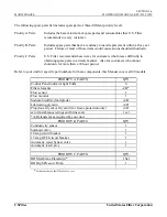
Page 38: ...ts in a timely manner Also for customers who cannot shutdown for more than a 24 hour period Refer to your unit for specific part numbers for these components this Manual covers all 20 models PRIORITY A PARTS QTY Control Panel indicator light bulbs 6 Filter elements A R Flow sensor 1 Flow monitor 1 Sodium bisulfite food grade A R Lubricating glycerin A R Propylene Glycol or Glycerol for freeze prot...

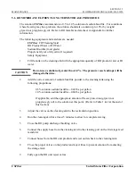
Page 39: ...e pressure vessel endcaps will be damaged otherwise 2 Add the correct amount of sodium bisulfite powder to the cleaning tank using the following proportions 0 5 solution sodium bisulfite 042 lbs per gallon 1 0 solution sodium bisulfite 084 lbs per gallon If applicable add the appropriate amount of freeze protection glycerin or propylene glycol to the solution at this point Refer to Table 1 2 at th...

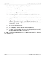
Page 40: ...e and a Lock Out Tag on the valve 16 If applicable you may also have to fully close any process valves located in the RO unit product line down stream of the product divert to drain valve junction to prevent unwanted RO product water from passing this point and install a Lock Out device and a Lock Out Tag on the valve 17 Drain the pump and manifold piping 18 Seal all openings to prevent the membra...

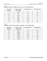
Page 41: ... 2 2 28 15 1 012 3 9 25 20 1 017 6 7 20 25 1 020 8 9 16 30 1 024 12 8 9 35 1 028 16 1 3 40 1 032 20 6 5 45 1 037 26 7 16 50 1 040 33 3 28 Table 2 FREEZING POINT OF GLYCEROL GLYCERIN WATER MIXTURES glycerin by WEIGHT Specific Gravity 15 0o C 59o F Freezing Point o C Freezing Point o F 10 1 02415 1 6 29 1 20 1 04935 4 8 23 4 30 1 07560 9 5 14 9 40 1 10255 15 5 4 3 50 1 12985 22 0 7 4 60 1 15770 33 6...

Page 42: ... a reduction in the NORMALIZED PRODUCTIVITY RATE a reduction in the RO UNIT TOTAL DISSOLVED SOLIDS REJECTION RATE or an increase in the RO UNIT OPERATING PRESSURE in spite of no change in the RO UNIT feed water temperature In general this procedure should not be required more then three 3 times per year or about every four 4 months If you find that this procedure is required more frequently then t...

Page 43: ...can do is try to take reasonable precautions through the possible use of ultraviolet sterilizers on the RO UNIT feed water conduct good maintenance procedures on the multimedia filters including periodic sterilization cycles and the use of approved biocides on the RO UNIT MEMBRANE ELEMENTS This type of foulant is evidenced by a gradual reduction in the NORMALIZED PRODUCTIVITY RATE with either no r...

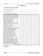
Page 44: ...Inlet Pressure PSI Feed Flow Rate GPM 2 Product Flow Rate GPM Reject Flow Rate GPM Reject Recirculation Flow Rate GPM Product Recovery 3 Feed Water Temperature o F Feed Water pH 0 14 Feed Water Chlorine Concentration PPM Feed Water Total Hardness PPM Feed Water SiO2 PPM as SiO2 Feed Water Conductivity mg l RO 1rst Stage Conductivity PSI RO 2nd Stage Conductivity mg l RO 3rd Stage Conductivity mg l...

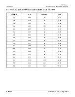
Page 45: ... is equal to the RO feed conductivity MINUS the RO product conductivity DIVIDED by the feed conductivity TIMES 100 EXAMPLE Feed conductivity 380 micromoh Product conductivity 5 micromoh 380 5 380 x 100 98 6 rejection the RO Quality monitor is set up at the factory to display this value 5 NORMALIZED PRODUCTIVITY is a true indication of membrane performance It is calculated as follows NPF MPF X TCF ...

Page 46: ...TION FACTOR TEMP o F TCF TEMP o F TCF 34 3 64 70 1 12 36 3 18 72 1 08 38 2 93 74 1 05 40 2 68 76 1 02 42 2 47 78 0 97 44 2 29 80 0 93 46 2 14 82 0 90 48 2 01 84 0 88 50 1 88 86 0 86 52 1 77 88 0 82 54 1 68 90 0 79 56 1 59 92 0 77 58 1 51 94 0 75 60 1 44 96 0 73 62 1 36 98 0 70 64 1 30 100 0 68 66 1 24 102 0 65 68 1 17 104 0 63 ...

Page 47: ...3 2 40 156 165 177 188 197 6M 5 3 48 188 200 212 225 237 6M 6 3 54 211 225 239 253 266 6M 6 4 60 235 250 265 281 296 6M 8 4 72 282 300 318 338 355 The recommended flux rate for maximum membrane life should not exceed 16 5 GFD NOTE VALUES LISTED ABOVE ARE NOMINAL FLOW RATES BASED ON AVERAGE FEED WATER CONDITIONS A CHANGE IN WATER TEMPERATURE AND OR WATER QUALITY CAN SIGNIFICANTLY ALTER THE ACHIEVAB...

Page 48: ...SECTION 6 5 APPENDIX FLOWMAX RO MANUAL REV B 05 1999 USFilter United States Filter Corporation 6 3 QA DATA SHEETS See QA Data sheet that follows this page ...

Page 49: ...SECTION 6 6 APPENDIX FLOWMAX RO MANUAL REV B 05 1999 USFilter United States Filter Corporation THIS PAGE INTENSIONALLY LEFT BLANK ...

Page 50: ...AWING S8601 026 FM6 48 PACKAGED SYSTEM EQUIP SPEC DRAWING S8601 027 FM6 54 PACKAGED SYSTEM EQUIP SPEC DRAWING S8601 028 FM6 60 PACKAGED SYSTEM EQUIP SPEC DRAWING S8601 029 FM6 72 PACKAGED SYSTEM EQUIP SPEC DRAWING S8601 030 FS3 09 PACKAGED SYSTEM EQUIP SPEC DRAWING S8601 031 FS3 12 PACKAGED SYSTEM EQUIP SPEC DRAWING S8601 032 FS3 18 PACKAGED SYSTEM EQUIP SPEC DRAWING S8601 033 FS4 24 PACKAGED SYST...

Page 51: ...SECTION 6 8 APPENDIX FLOWMAX RO MANUAL REV B 05 1999 USFilter United States Filter Corporation THIS PAGE INTENSIONALLY LEFT BLANK ...

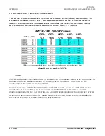
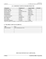
Page 52: ... Structures 80A Series RO Membranes Filmtec BW30 365 RO Membranes Filmtec BW30 400 RO Membranes Filmtec BW30 440LE Rejection Monitor Thornton 200CR PLC Micrologix Allen Bradley 1000 Flow Sensor Fluidyne 2300 Flow Monitor Thornton 200F pH Monitor optional Thornton 200pH Only the literature that applies to your system will be included in this section 6 6 MATERIAL SAFETY DATA SHEET S Title Use Sodium...

Reviews: