


4
Read and follow ALL instructions.
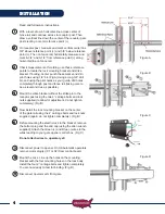
With a level, draw a horizontal line across center of
fence rail and continue across to receptor post. Then
draw a vertical line down the center of the receptor gate
post creating a center reference point (+).
On receptor post, measure and mark vertical center line
3/8” above reference point (+) and 3/8” below reference
point (+). Then on fence rail, horizontally measure and
mark 6-3/4” and 9-1/4” from reference point (+) along
horizontal line on fence rail.
Check measurements. If welding, use these reference
points to locate the lock mounting bracket and strike
bracket. If bolting, center punch these marks and drill
pilot holes using 1/8” bit. (Fig A) Using a long 3/8” drill
bit, and using the pilot holes as your guide, drill holes
completely through post and fence rail (taking care to
be as level and true as possible).
Mount the strike bracket without the strike pin to the
receptor post using the two 6” carriage bolts and lock
nuts supplied (to allow for adjustment, do not tighten
completely). (Fig B)
Now install the lock mounting bracket on the center
of the gate rail using the 4” carriage bolts and lock nuts
supplied (again, do not tighten completely). (Fig B)
Before mounting the electric lock to the bracket, remove
the bottom plug and the end cap (using the allen wrench
supplied). Attach the Green (+) and Blue (-) wires to the
wires leading to your gate opener control box. (Fig C)
Do not attach wires to operator yet!
Disconnect power to opener. On USAutomatic operators,
remove motor plug(s) (X1 or X2) from control board.
Mount the Lock. Line up the holes on the mounting
bracket with the four mounting holes on the lock body.
Install the four 2” carriage bolts and tighten completely.
You are now ready to test for binding. (Fig. D)
Disconnect operator arm from gate.
8
9
7
Figure D
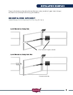
INSTALLATION
1
2
3
4
5
6
Figure A
Figure B
Figure C