background image

SYSTEM MAINTENANCE

MANOWNROSM

US Filter

16

2. 

Hydrogen Peroxide


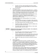
Advantages of using hydrogen peroxide are that it has no toxic vapors, is
biodegradable, is easily disposable, has good biocidal activity, and
breaks down into oxygen and water, which does not harm the
environment.  Because of these qualities, operators can be assured that
they are not handling toxic materials.

3. 

Peracetic Acid


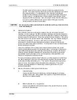
Advantages of using peracetic acid are that it has no toxic vapors, is
biodegradable, easily disposable, and has good biocidal activity.
Because of these qualities, operators can be assured that they are not
handling toxic materials.  Peracetic acid decomposes into oxygen, water,
and acetic acid, which does not harm the environment.  Several peracetic
acid solutions are commercially available, including; Minncare and
Renalin Dialyzer Reprocessing Concentrate, both products of Minntech
Corporation, and P3-Oxonia Active, a product of Henkel Corporation.  For
ordering information call the number provided on the cover of this
manual.

B. 

Selecting a Sanitant

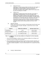
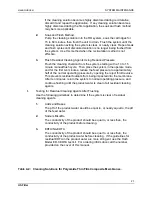
Table 4-1 lists the type and concentration of sanitizing agent that should be used
for polyamide thin film composite cartridges, as well as the minimum contact
time for sanitization.

Sanitant

Sanitant Concentration

Sanitant Contact Time

Formaldehyde *

2-3%

30-60 minutes

Hydrogen Peroxide **

up to 2000 ppm (0.2%)

30-60 minutes

Peracetic Acid **

up to 2000 ppm (0.2%)

30-60 minutes

Table 4-1: Sanitization Times and Concentrations for Polyamide Thin Film Composite

Cartridges.

*

When using formaldehyde to sanitize thin film composite cartridges, the cartridges must
have been in use for 24 hours prior to sanitization.

**

When using hydrogen peroxide or peracetic acid with thin film composite membranes, the
temperature should not exceed 25

°

 C (77

°

 F). Also, the presence of iron or heavy metals

can cause membrane degradation.  Clean the membranes first if iron is present in the feed
water.

C. 

Testing for Residual Sanitant

Summary of Contents for M SERIES - 2000

Page 1: ...Operation and Maintenance Manual for M SERIES 2000 Reverse Osmosis Systems For Dialysis Applications Serial ________________________ 8 97 MANOWNROSM REV F ...

Page 2: ......

Page 3: ...NS There are no absolute contraindications to reverse osmosis water treatment CAUTIONS AND WARNINGS Procedures using the Reverse Osmosis System must be performed under the direction of a physician Prior to operating or servicing this device this manual must be read and understood If something is not clear call for assistance before proceeding Keep this and other associated manuals for future refer...

Page 4: ...n connection with or arising from the use of this manual Copyright 1999 United States Filter Corporation Printed in the United States of America All rights reserved THIS BOOK OR PARTS THEREOF MAY NOT BE REPRODUCED IN ANY FORM WITHOUT THE WRITTEN PERMISSION OF THE PUBLISHERS PROPRIETARY RIGHTS STATEMENT This manual discloses information in which US Filter has proprietary rights Neither receipt nor ...

Page 5: ... observed to avoid personal injury or fatalities CAUTION Cautions indicate a situation that may cause damage or destruction of equipment or may pose a long term health hazard NOTE Notes are used to add information state exceptions and point out areas that may be of greater interest or importance EQUIPMENT SUPPORT US Filter continually strives to provide safe efficient trouble free equipment using ...

Page 6: ......

Page 7: ...ry Sensors Pretreatment Interlock and Tank Level 2 2 2 8 Setting the Flush Cycle Time Optional 2 3 2 9 Before Power Turn On 2 3 2 10 Installation of Reverse Osmosis Membrane s 2 3 3 0 OPERATING INSTRUCTIONS 3 1 Controls and Indicators 3 1 3 2 Initial Startup of Reverse Osmosis System 3 1 3 3 Initial Flushing of the System 3 2 3 4 Normal Operations 3 2 3 5 Shutdown Less Than 4 Days 3 3 3 6 Prolonge...

Page 8: ...2 5 9 System Shutoff High Temperature 5 3 5 10 Low Permeate Flow Rate 5 3 5 11 Motor Overload Shutdown 5 3 5 12 Controller Malfunction 5 3 6 0 warranty 6 1 General Limited Warranty 6 1 6 2 Water System Limited Warranty 6 1 7 0 appendix 7 1 TABLE DESCRIPTION PAGE 4 1 Sanitization Times and Concentrations for Polyamide 4 2 Thin Film Composite Cartridges 4 2 Cleaning Solutions for Polyamide Thin Film...

Page 9: ... impurities is not passed through the membrane and is rejected to drain Prefilters are used in many systems to reduce the amount of particulate contamination reaching the membrane thus insuring the membrane does not become clogged Please refer to general membrane specifications and System Specifications Sheet in the Appendix for other parameters important to the operation of the system 1 2 QUALITY...

Page 10: ...t damaging pressures from reaching the RO membranes This switch immediately shuts off the RO pump if the pressure exceeds safety limits D Pump Throttle Valve A pump throttle valve is used to control the pressure and volume of water supplied to the RO membranes E Reverse Osmosis Membranes The prefiltered water enters the RO housing and passes over the surface of the RO membrane A portion of the fee...

Page 11: ... temperatures 4 Low percent rejection alarm The alarm function is activated when the percent rejection falls below determined limits to warn the operator if the product water quality no longer meets specifications 5 Pump startup delay There is a ten second delay after turning on the unit before the pump starts 6 Automatic flush The system automatically flushes each hour when the system is in the S...

Page 12: ...lowing conditions Low Feed Pressure High Pressure to Membranes High Feed Temperature Tank Full Pretreatment Interlock Low Percent Rejection As these units are normally installed in a location away from patient areas for noise containment an accessory audible alarm is necessary to comply with AAMI standards The controller generates a signal to drive this alarm for the following conditions Low Feed ...

Page 13: ... gauges control box pump valves and regulators are all pre mounted on the main frame and factory set to correct values Carefully remove from the packing crate to avoid damage to gauges RO membranes etc Do not drop or handle with excessive roughness to prevent damage to the electronic components and to prevent damage to the piping joints 2 3 SYSTEM LOCATION A drain capable of handling the flow of r...

Page 14: ...TANK LEVEL Provisions have been made for shutdown by accessory sensors provided such sensors are equivalent to a single pole single throw switch The shutdown is such that normal operation will resume automatically when the failure is removed A Remove the lower panel from the control box and the attached integrated controller circuit to expose the terminal connections B See the Reverse Osmosis Cont...

Page 15: ...sodium bisulfite solution However should the need arise the following procedures may be followed to install membranes A See the Appendix for a diagram of the individual components of the membrane assembly Before sliding the membranes into the fiberglass housing install the proper product tube adapters on in the product tube Lightly lubricate the o rings with glycerin B Load the RO membrane into th...

Page 16: ......

Page 17: ...ions CAUTION Verify that all RO housing retaining rings are in place and engaged D Turn on the Key switch and press the power button Place the controller in the Direct Feed Mode E Check for proper pump rotation Slowly close the pump throttle valve Figure 1 1 and record the pressure indicated on the PUMP PRESSURE gauge upstream of the valve Immediately turn the system off DISCONNECT THE POWER and s...

Page 18: ... replacement of a RO membrane perform the following steps A Place the outlet of the permeate at a convenient drain B Turn on the feedwater and the system pump as outlined in Operating Instructions Initial Startup of the Reverse Osmosis System section of this manual and let the system run for 24 hours This will flush residual bisulfite solution and any particulate impurities from the membranes hous...

Page 19: ...OWN LESS THAN 4 DAYS If the system is not to be run for up to 4 days the system should be placed in the STANDBY mode of operation This will allow the system to return to operation at any time with no adverse affects on the permeate or membranes CAUTION If the shutdown is due to a malfunction be sure to disconnect the electrical power and turn off the water supply before making repairs or replaceme...

Page 20: ...the permeate water to drain for 4 hours to flush the system The product water should be analyzed with the Fast Formalert or other formaldehyde test kit until detection limits are reached Reattach the permeate line and start the system as outlined in the Operating Instructions Normal Operations section of this manual ...

Page 21: ... bacterial levels in the feed and permeates as needed When bacterial levels increase above an acceptable level for the application sanitize the system The choice of the sanitizing agent depends on its compatibility with the polyamide thin film composite RO cartridges and system components and the agent s effectiveness as a sanitant Three commonly used sanitants are formaldehyde hydrogen peroxide a...

Page 22: ...h Corporation and P3 Oxonia Active a product of Henkel Corporation For ordering information call the number provided on the cover of this manual B Selecting a Sanitant Table 4 1 lists the type and concentration of sanitizing agent that should be used for polyamide thin film composite cartridges as well as the minimum contact time for sanitization Sanitant Sanitant Concentration Sanitant Contact Ti...

Page 23: ...d Static Soak 1 Continuous Injection Method In this method of sanitization an accessory chemical feed system injects concentrated sanitant into the feed line while the RO is operating at normal flows and pressure Both the product and reject streams are sent directly to drain The continuous injection method is most typically used to sanitize with hydrogen peroxide It is not practical for formaldehy...

Page 24: ...ter pump is turned on and the RO is run in the normal operating mode for 30 to 60 minutes CAUTION Monitor the solution temperature during recirculation Do not allow the temperature to exceed 25 C e The booster pump and the RO system are shut down and the sanitant is allowed to sit in the system optional f The RO is switched back to the normal feed source and run in the normal operating mode with t...

Page 25: ...ecreases or malfunctioning pretreatment systems pressure controls and pumps may also cause these conditions It is important to rule out these factors before cleaning the system Clean the cartridges if the system performance based on flow rate or salt rejection decreases because of membrane fouling An increase in the feed to reject differential pressure also indicates that cleaning is needed Membra...

Page 26: ...e flow keeps foulants within or on the membrane surface during cleaning Optimally a high flow low pressure accessory cleaning pump should be used 3 The temperature must not exceed 35 C The temperature of the cleaning solution must not exceed 35 C It may be necessary to install a heat exchanger to prevent the temperature from exceeding 35 C The optimum temperature of the cleaning solution is 25 C t...

Page 27: ...ed pressure to approximately half of the normal operating pressure by opening the reject throttle valve This prevents residual foulants from being impacted into the membrane After ten minutes return the system to normal operating pressure and continue flushing until the product water is clear of all residual cleaning agents I Testing for Residual Cleaning Agents After Flushing Use the following gu...

Page 28: ... 0 2 x x Sodium Hydrosulfite 2 4 x Prepare sodium bisulfite using a buffered solution of 0 1 Na2CO3 or 0 15 NaHCO3 J Preparing the Cleaning Solutions Use the following procedures to make 10 liters L of solution For larger volumes increase chemical amounts accordingly The total volume of cleaning solution depends on the system size A minimum of 100 liters is recommended WARNING Use caution when pre...

Page 29: ... makeup water Check the addition of acid with a pH meter 6 Sodium Hydroxide pH12 The amount of NaOH needed will vary depending on the makeup water quality If solid NaOH pellets are available add 4 0 40g to 10L of RO water Check the addition of caustic with a pH meter If 50 NaOH is used start with 5ml per 10 liters and add until a pH of 12 is reached K Shutdown Procedures 1 Short Term Shutdown Less...

Page 30: ...more frequent monitoring schedule may be necessary for patient safety Consult your US Filter representative for assistance A Feedwater 1 Check pressure daily record weekly Adjust as necessary to maintain 0 69 to 6 9 bar 10 to 100 psi 2 Monitor feed and permeate conductivity and record weekly 3 If there is a possibility of the presence of chlorine in the feedwater measure free chlorine weekly It mu...

Page 31: ...te Reject Flow Rate The percent recovery should not exceed the design value shown on the System Specifications sheet in the Appendix If minimizing water usage is critical the percent recovery should be maintained near but not above the maximum value Operating with too high a percent recovery will lead to premature fouling of the membrane G Calcium Measure the feed and permeate calcium and calculat...

Page 32: ......

Page 33: ...ump backwards for more than 30 seconds or irreversible damage will result C Check to verify that the reject reject recirculation and product flows are normal If not adjust to design flow rates using the System Specifications sheet in the Appendix D If the flows cannot be adjusted to the desired flow rates slowly close the pump discharge throttle valve to observe the maximum discharge pressure Do t...

Page 34: ...ct the calcium rejection C RO membrane o rings may not be seated correctly Remove membrane and verify that the o rings are in good condition and seated correctly D The RO membrane requires cleaning or replacement 5 7 SYSTEM KEEPS SHUTTING OFF A Observe the control box lights to see if they indicate the cause for system shutdown B Overload relay tripped If the overload relay requires resetting freq...

Page 35: ... suspected various regeneration cleaning solutions may be used Consult your US Filter representative for advice CAUTION Certain solutions especially those containing chlorine or bromine can permanently damage the membranes 5 11 MOTOR OVERLOAD SHUTDOWN A Motor overload shutdown is caused by excessive amp draw An overload relay is provided with the motor magnetic starter to shut the system down if i...

Page 36: ......

Page 37: ...le for consequential damages resulting from economic loss or property damages sustained by a customer from the use of its products 6 2 WATER SYSTEM LIMITED WARRANTY United States Filter Corporation USF warrants the water systems manufactured by it BUT EXCLUDING MEMBRANES AND CARTRIDGES against defects in materials and workmanship when used in accordance with the applicable instructions and within ...

Page 38: ...ulting from economic loss or property damages sustained by any customer from the use of its process systems Products or components manufactured by companies other than USF or its affiliates Non USF Products are covered by the Warranty if any extended by the Product manufacturer USF hereby assigns to the purchaser any such warranty however USF EXPRESSLY DISCLAIMS ANY WARRANTY WHETHER EXPRESSED OR I...

Page 39: ...ulting from water transport through the semipermeable membrane separating two saline solutions of different concentrations PASSAGE Ratio of permeate to feed concentration of a particular dissolved material expressed in percent PERMEATE PRODUCT The purified portion of the feed passing through the membrane REVERSE OSMOSIS RO The process by which incoming fluid feed is forced under high pressure thro...

Reviews: