©
U
.S
B
LA
ST
ER
D
es
ig
n
-U
SA
-P
.O
.B
ox
53
76
-C
ar
ef
re
e
-A
Z
85
37
7.
USB 7392 - 7393
Microphone systems
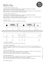
5. A-Channel Symmetrical Output
This socket is an audio output for the A-channel of the transmitter. Connect this output to the micro-
phone input of your audio mixer or directly to an input of your amplifier.
Note: It is a symmetrical output. Therefore, use a symmetrical cable and XLR connector.
6. A-Aerial Connector
Connect the aerial (supplied with the microphone set) to this socket.
PUTTING THE RECEIVER INTO OPERATION
- Connect both aerials to the sockets designed for them (A and B).
- Direct them to a 90Y direction in relation to the receiver.
- Connect the DC 12V power supply to the power supply connector.
Warning: Do not connect other types of power supply (an AC one or a DC one supplying more than
12V). Otherwise, it may result in damage to the receiver..
- Set the volume adjustment buttons for each channel to minimum and, then, press the On/Off but-
ton and hold it depressed for 1 to 2 seconds.
- By using the Up and Down buttons, set working frequencies for each channel and, then, confirm the
frequencies by pressing the Set button.
Note: Receiver are specifications are included below in this operating manual.
- To turn the receiver off, press the On/Off button (2) and hold it depressed for 1 to 2 seconds. The
LCD will show “SYSOFF”.
LCD DISPLAY DESCRIPTION
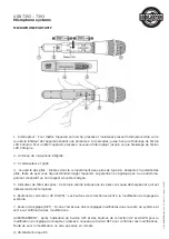
1. RF Indicator
It indicates the level of RF signal (the signal received from the microphone).
2. AF Indicator
It indicates the level of AF signal (channel output signal).
3. Working frequency
It indicates the frequency used in operation.
4. A Aerial Indicator
As it is a selective reception receiver, it chooses the aerial via which the reception is the best. If the
display shows 1, it means that reception is carried out by means of the A aerial.
5. B Aerial Indicator.
As it is a selective reception receiver, it chooses the aerial via which the reception is the best. If the
display shows Il, it means that reception is carried out by means of the B aerial.
6. Sound Attenuation Indicator
This logo is to inform you of the fact that the unit operates in the “mute” mode (that means that no
sound is at the channel output – either nobody speaks into the microphone or the receiver frequen-
cy differs from the transmitter frequency).
© US Blaster Europe BV


