background image

E N G L I S H

45

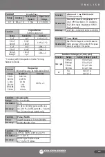
Function 

Diode Test

Range

Accuracy

Test Current

(Typiacl)

Open Circuit 

Voltage

4 V

2% + 1

1 mA

< 3.0 V DC

Function 

Capacitance

(5.000 counts only)

Range

Resolution

Accuracy

5 nF

1 pF

1.0% + 5 *2

50 nF

500 nF

10 pF

100 pF

1.0% + 3 *2

5 µF

1 nF

2.0% + 3

50 µF

10 nF

3.0% + 3

500 µF

5000 µF

100 nF

1 µF

3.5% + 3

*1 Accuracy with film capacitor or better *2 Using 
Relative (∆) mode.

Function 

Frequency

[Minimum Frequency; 0.5 Hz Sensitivity: 250 mV]

Range

Resolution

Accuracy

50 Hz

500 Hz

5 kHz

50 kHz

500 kHz

5 MHz

0.001 Hz

0.01 Hz

0.1 Hz

1 Hz

10 Hz

100 Hz

0.01% + 3

Function 

Duty cycle

Range

0.1% to 99.9%

Resolution

0.1%

Accuracy

0.5 Hz to 300 kHz (pulse width >3 µ 
sec.) (0.1% + 0.05% per kHz + 1 count) 
for 5 V input (Logic signals only)

Function 

Pulse Width

Range

Input Frequency 0.5 Hz to 300 kHz

Accuracy

Ancho de pulso >3 µ s

Function 

Temperature

Range

-50°C to 1300°C (-58°F to 2372°F)

Resolution

0.1° C (0.1° F)

Accuracy

with K-type Thermocouple
± 3°C (± 5.4°F) typical

Function 

dBm and 1 ms PEAK Hold
(5.000 counts only)

Characteristics

Selectable reference impedance of 1 
Ω to 1.999 Ω At 600 Ω: -11.76 dBm to 
54.25 dBm Input impedance: 10 MΩ, 
30 pF nominal

Accuracy

±0.25 dB + 2 digits (@ 40 Hz to 20 kHz)

Function 

1 ms PEAK

Characteristics

Specified voltage or current measure-
ment accuracy ±30 counts of the peak 
value of a single 1 ms pulse.

Burden Voltage ( A, mA, μA )

Function

Range

Burden Voltage (Typical)

mA / µA

500 µA

5000 µA

50 mA

500 mA

150 µV / µA
150 µV / µA
3.3 µV / mA
3.3 µV / mA

A

5 A

10 A

0.03 V / A
0.03 V / A

Summary of Contents for UD87

Page 1: ...ENCI N Lea entienda y siga las instrucciones de seguridad contenidas en este documento antes de operar esta herramienta WARNING Read understand and follow the safety rules in this document before oper...

Page 2: ...IALES 6 MANTENIMIENTO 7 ESPECIFICACIONES ADVERTENCIA ONDAS COMO LAS DE PEQUE OS RADIOS PORT TILES TRANSMISORES TRANSMISORES DE ESTACIONES DE RADIO Y TELEVISI N TRANSMISORES DE RADIO DE VEH CULO Y DE T...

Page 3: ...AJAR CON VOLTAJES MAYORES A 60V CD O 30V CA RMS ESTOS NIVELES DE VOLTAJE PROPICIAN UN RIESGO DE DESCARGA POTENCIAL PARA EL USUARIO INSPECCIONE LOS CONECTORES DE PRUEBA PUNTAS Y SONDAS CUALQUIER AISLAM...

Page 4: ...erfase ptica RS 232 Glosario de t rminos Promedio RMS Calibrado RMS Root Mean Square es el t rmino utilizado para describir la eficacia o equivalencia de un valor CD de una se al CA La mayor a de los...

Page 5: ...R es la capacidad de un DMM de rechazar el voltaje en modo com n el cual puede causar el parpadeo de un d gito o variaci n en las mediciones de voltaje El Medidor tiene una especificaci n de CMRR 60dB...

Page 6: ...diciones de CD de 0 mV a 500 mV y aplicaciones de adaptadores Despliegue Selecci n de Men en pantalla Cuando la tecla del men se encuentra presionada Despliegue Primario Secundario Primario Secundario...

Page 7: ...a tecla del men se encuentra presionada Despliegue Primario Secundario Primario Secundario C SET F Medici n default de corriente CD de 0 A a 5000 A Despliegue Selecci n de Men en pantalla Cuando la te...

Page 8: ...nte en este modo 1ms PEAK Presione este bot n moment neamente para activar el modo 1ms de retenci n de cresta para capturar voltaje transitorio o eventos de se al de corriente tan cortos como 1ms con...

Page 9: ...ionar el bot n HOLD o ver la pantalla del medidor durante el sondeo y toma de mediciones MEM Utilice este modo de memoria para guardar y llamar valores de medici n Presione el bot n MEM moment neament...

Page 10: ...an en una EEPROM para que no puedan perderse cuando se ha apagado el medidor Habilitando o deshabilitando el modo de auto apagado El medidor muestra en la pantalla secundaria o en la pantalla primaria...

Page 11: ...municaciones RS 232C de la PC al medidor El medidor se encuentra equipado con un puerto de interfase pticamente aislado en la parte superior para la transferencia de datos El cable del adaptador ptico...

Page 12: ...la primaria CD Pantalla secundaria Medici n dBm Teclas del men dBm o dB presione para cambiar Conexi n de puntas de prueba fig A Pantalla primaria CA Pantalla secundaria dBm Medici n dB Teclas del men...

Page 13: ...uede ajustarse a cualquier valor entre 1 y 1999 usando los botones de ajustes del men En el momento de la medici n de dB V el voltaje de referencia puede ajustarse a cualquier valor de 0 1000 V a 5 00...

Page 14: ...men sin selecci n Conexi n de puntas de prueba fig A Pantalla primaria Hz Pantalla secundaria Medici n Doble pantalla de frecuencia y ciclo de trabajo Teclas del men Conexi n de puntas de prueba fig...

Page 15: ...formas de onda medidas deben ser peri dicas Resistencia y Mediciones Resistencia Continuidad y Capacitancia PRECAUCI N PARA EVITAR DA O AL MEDIDOR O AL EQUIPO BAJO PRUEBA INTERRUMPA TODA LA ENERG A DE...

Page 16: ...funcionamiento de interruptores Un tono beep continuo indica un cableado cerrado PRECAUCI N UTILIZAR LA FUNCI N DE RESISTENCIA Y CONTINUIDAD EN UN CIRCUITO ENERGIZADO PRODUCIR RESULTADOS FALSOS Y PUE...

Page 17: ...irecta para un diodo de silicio en buenas condiciones se encuentra entre 0 4V y 0 9V Una lectura superior a esta indica un diodo con fuga defectuoso Una lectura de cero indica un diodo en corto defect...

Page 18: ...as de prueba fig G Pantalla primaria F Pantalla secundaria Medici n CA CA RMS totales Teclas del men CA CD o CA CD presione para cambiar Conexi n de puntas de prueba fig G Pantalla primaria CA CD Pant...

Page 19: ...el rango en el que estaba cuando el indicador se apag Presione el bot n de nuevo durante un momento para desplazarse a trav s de los rangos Presione y sostenga el bot n RANGE durante dos segundos o m...

Page 20: ...ara la entrada de corriente A ADVERTENCIA PARA EVITAR LECTURAS FALSAS QUE PODR AN LLEVAR A UNA POSIBLE DESCARGA EL CTRICA O LESI N PERSONAL REEMPLACE LA BATER A EN CUANTO EL INDICADOR DE LA BATER A BA...

Page 21: ...omagn tica EMC Susceptibilidad l mites comerciales para EN 50082 1 Emisiones L mites comerciales para EN 50081 1 Tama o A x A x P 208 x 103 x 54 mm no incluye accesorios montados Peso Aprox 655 g Gara...

Page 22: ...l Factor de la Cresta 3 1 a una escala completa y 6 1 a media escala Funci n Volts CD Rango Resoluci n Precisi n 50 mV 10 V 0 1 3 500 mV 5 V 50 V 500 V 1000 V 100 V 1 mV 10 mV 100 mV 1 V 0 1 3 NMRR 60...

Page 23: ...dida es menor a 10 y se apaga cuando es mayor de aproximadamente 70 Tiempo de respuesta 1 ms Funci n Prueba de Diodo Rango Precisi n Corriente de Prueba T pico Voltaje de Circuito Abierto 4 V 2 1 1 mA...

Page 24: ...ble de 1 a 1 999 A 600 11 76 dBm a 54 25 dBm Impedancia de entrada 10M 30 pF nominal Precisi n 0 25 dB 2 d gitos 40 Hz a 20 KHz Funci n 1 ms PEAK Caracter sticas Voltaje espec fico o precisi n de la m...

Page 25: ...D SPECIAL FEATURES 6 MAINTENANCE 7 SPECIFICATIONS WARNING SOURCES LIKE SMALL HAND HELD RADIO TRANSCEIVERS FIXED STATION RADIO AND TELEVISION TRANSMITTERS VEHICULE RADIO TRANSMITTERS AND CELLULAR PHONE...

Page 26: ...A POTENTIAL SHOCK HAZARD TO THE USER INSPECT TEST LEADS CONNECTORS AND PROBES FOR DAMAGED INSULATION OR EXPOSED METAL BEFORE USING THE METER IF ANY DEFECTS ARE FOUND REPLACE THEM IMMEDIATELY DO NOT T...

Page 27: ...se average sensing RMS calibrated technique to measure RMS values of AC signals This technique is used to obtain the average value by rectifying and filtering the AC signal The average value is then s...

Page 28: ...contributes measurement error and should be as low as practical Temperature Coefficient Temperature Coefficient is a factor used to calculate the change in indication or output of an instrument with...

Page 29: ...Primary Secondary DC AC AC Hz AC DC or dual display AC DC total RMS Volts Hz AC DC AC Volts and dBm or dB measurement Display On screen menu selection When the menu key is pressed Display Primary Seco...

Page 30: ...AC Hz DC DC DC current measurements default from 0 mA to 10 A Display On screen menu selection When the menu key is pressed Display Primary Secondary Primary Secondary DC AC AC Hz AC DC o AC DC or du...

Page 31: ...s button to set the meter to relative mode and make relative measurements The reference value for the measurement can be a measured or a programmed value The reference value appears in the secondary d...

Page 32: ...mary display is erased When you press the AC key all the stored values are erased and the word shows on the display Press EXIT key to exit memory mode without erasing the stored values EXIT Select EXI...

Page 33: ...on screen menu selection You can toggle by pressing the menu keys Press the EXIT menu key to get into the next Setup Enable or Disable the beep alert warning overranges The meter displays in the secon...

Page 34: ...e Measurements Ranges available in Volts functions are 50 mV 500 mV DC and 500 mV AC Measurement DC Millivolts default Menu key no selection Connect leads fig A Primary display DC Secondary display DC...

Page 35: ...s in the secondary display and the AC reading appears in the primary display Normally dB is measured as dBm which is a measure of decibels relative to 1 milliWatt The meter assumes a resistance of 600...

Page 36: ...x frequency ranges 50 000 Hz 500 00 Hz 5 0000 KHz 50 000 KHz 500 00 KHz and 5 0000 MHz The meter beeps to indicate when a particular pushbutton is not allowed when measuring frequency The 1ms Peak but...

Page 37: ...r low within a given period The measured waveform must be periodic Resistance and Measurements Resistance Continuity and Capacitance CAUTION TO AVOID DAMAGING THE METER OR THE EQUIPMENT UNDER TEST REM...

Page 38: ...Y CASES THE SUSPICIOUS COMPONENTS MUST BE DISCONNECTED FROM THE CIRCUIT UNDER TEST TO OBTAIN ACCURATE RESULTS The 1 ms PEAK MIN MAX and REL functions are not available when continuity is selected Cond...

Page 39: ...rature Temp Measurements WARNING DO NOT APPLY THERMOCOUPLE TO CIRCUITS EXCEEDING 30V RMS 42 4V PEAK OR 60V DC Measurement Celsius Temperature default Menu key no selection Connect leads fig F Primary...

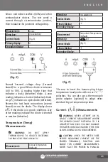
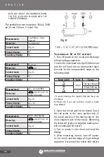
Page 40: ...sure AC or DC current 1 Turn off power to the circuit and discharge all high voltage capacitors 2 Insert the black lead into the COM terminal and the red lead into an appropriate input terminal for th...

Page 41: ...continuity while in continuity mode Auto Power Off The Auto Power Off feature has two steps The first step has the meter automatically go into the power saving mode to extend battery life after approx...

Page 42: ...age transient caused by lightning or switching surge to the system by accident or abnormal operating conditions the series fusible resistors will be blown off like fuses in order to protect the user a...

Page 43: ...rage values 1ms PEAK Mode Captures peaks to 1 millisecond Close Case Calibration No internal adjustments needed Battery Fuse Access Door Battery or fuse replaceable without voiding Calibration High im...

Page 44: ...kHz 1 kHz 10 kHz 500 A 5 mA 50 mA 500 mA 100 nA 1 A 10 A 100 A 0 5 2 1 0 5 5 A 10 A 1 mA 10 mA 0 8 10 Unspecified AC DC voltage and AC DC Current Function Range Resolution Accuracy 40 Hz 1 kHz 1 kHz 1...

Page 45: ...kHz pulse width 3 sec 0 1 0 05 per kHz 1 count for 5 V input Logic signals only Function Pulse Width Range Input Frequency 0 5 Hz to 300 kHz Accuracy Ancho de pulso 3 s Function Temperature Range 50...

Page 46: ...46 NOTAS NOTES...

Page 47: ...47 NOTAS NOTES...

Page 48: ...s casos a Cuando la herramienta se haya utilizado en condiciones distintas a las normales b Cuando el producto hubiera sido alterado de su composici n original o reparado por personas no autorizadas p...

Reviews: