


10
DS1060-148
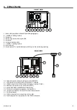
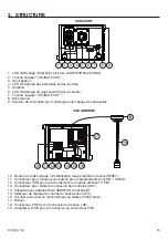
4. DESCRIPTION OF TERMINALS
]
PA
Hall button
]
SE2
Garage relay contacts
SE -
Pedestrian electrical lock with capacitance discharge actuation negative
SE +
Pedestrian electrical lock with capacitance discharge actuation positive
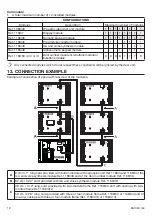
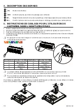
5. WIRING INSTRUCTIONS FOR THE USE OF THE DEVICE
WITHOUT THE RJ45 ADAPTER
Remove the RJ45 adapter (19) from the POE connector (18).
Remove the insulation sheath of the CAT5/CAT5E cable (with rigid wires) for at least 40 mm.
Strip the conductors for no more than 6mm.
Insert the wires in the connector (18) respecting the positions and colour codes shown (Standard
T568B).
Pressing the orange clips on the terminal block with a screwdriver makes it easier to insert the
conductors into the terminal block.
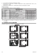
Wire No.
Wire colour
Wire No.
Wire colour
1
White-Orange
5
White-Blue
2
Orange
6
Green
3
White-Green
7
White-Brown
4
Blue
8
Brown
Wires with cross-section area of 0.5 mm
2
or larger must comply with IEC 60332-1-2; wires with
cross section area smaller than 0.5 mm
2
must comply with IEC 60332-2-2.
Refer to the instructions contained in the system manual for maximum distances and con
fi
guration
operations.
To insert the USB cable, if using a display module and ILA cable, if using an ILA and voice synthesis module,
follow the instructions below.
1
2
USB
ILA
•
•
•
•
1
8


