background image

6

Total Control

TKP-5600

Owner’s Manual

Main Menu: View Modes

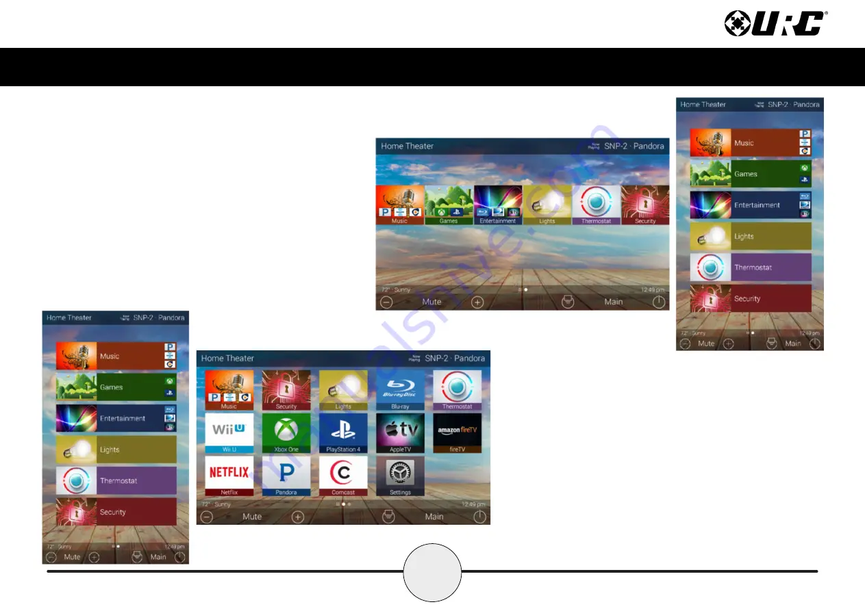
Total Control features two different view modes for the
TKP- 5600. Each view mode has its own unique properties
that compliment the user experience.

The view mode must be programmed from within the Accelerator
software, speak to a custom home integrator for more details.

1. Ribbon View:

This is the default view mode and it

contains up to six (6) items per page.

Ribbon View (Landscape & Portrait)

2. Grid View:

This view mode contains

up to fifteen (15) items per page.

Grid View (Landscape & Portrait)

Summary of Contents for Total Control TKP-5600

Page 1: ...TKP 5600 Owner s Manual Total Control TKP 5600 Owner s Manual ...

Page 2: ... Support Toll Free 800 904 0800 Main 914 835 4484 techsupport urc automation com Hours 9 00am 5 00pm EST M F Features and Benefits 1 Updated User Experience 1 Audio Video Interface 1 Proximity Sensor 2 Flexible Orientation 2 Installation 4 Wall Mounting 4 Main Menu Navigation 5 Main Menu View Modes 6 Title Bar 7 Room s Menu 8 Room Linking 9 Now Playing 10 Core Buttons 11 Shortcut Popup Menu 12 Add...

Page 3: ...is device has the capability of using URC s Total Control software suite Using this software provides this device with a modern look and feel giving the end user an improved user experience in terms of graphics performance and features Audio Video Interface Communicate with any other URC Intercom Enabled device in the system with this feature The end user can make Audio Video Audio or Audio Broadc...

Page 4: ...istances from up to three 3 feet away This setting can be adjusted in the device s Settings menu Flexible Orientation The TKP 5600 offers the ability to display the device in either portrait or landscape mode making it the perfect keypad for almost any room This feature can only be set from within the Accelerator software speak to a custom home professional prior to installation ...

Page 5: ...3 Total Control TKP 5600 Owner s Manual Part List Included in the TKP 5600 1x TKP 5600 Network Keypad 1x Mounting Ring 4x Mounting Screws TKP 5600 Mounting Ring Mounting Screws ...

Page 6: ...h data along Ethernet cabling A shielded Ethernet cable is preferred The IEEE standard for PoE requires a Category 5 or higher for high power levels Wall Mounting Follow the steps below for installation 1 Assure the one gang opening is fitted with the standard one gang retro box available at almost any electronic supplier 2 Mount the wall plate to the two gang retro box 3 Connect the Ethernet cabl...

Page 7: ...ibbon Select a Category button to reveal the associated sub menu OR select a Device located here to access that devices menu This is dictated by the custom integrator B Rooms Menu Select the Room Name to access the Room s Menu This menu allows the end user to control another room and more C Volume Control Tap the minus Vol to lower the volume plus Vol to increase the volume and Mute to mute the vo...

Page 8: ... that compliment the user experience The view mode must be programmed from within the Accelerator software speak to a custom home integrator for more details 1 Ribbon View This is the default view mode and it contains up to six 6 items per page Ribbon View Landscape Portrait 2 Grid View This view mode contains up to fifteen 15 items per page Grid View Landscape Portrait ...

Page 9: ...o access its menu swipe down as depicted on the image to the right There are three 3 selectable options here 1 Close Select this to hide the Title Bar Menu 2 Weather Module Select this to display the Time and Weather Module this feature requires the home location This location is set from within the Accelerator software 3 Intercom Select this button to display the Intercom Menu This menu displays ...

Page 10: ...Volume Control Select this button to reveal the Vol Vol and Mute icons This button is available on any room with audio sources 2 Lights Off Action Command This button is programmed by the custom integrator and can be set to turn off all the lights in a particular room 3 Room Off Select this button to turn off all the devices in that particular room This button can only be used to turn off a room 4...

Page 11: ...his displays the Room Linking Menu 2 Select which rooms in the system to link Only rooms that are DMS Zones Areas appear on the Room Linking Menu 3 Select the Check to confirm These rooms are now linked It is possible to control volume on all of these rooms from one menu see below Control the volume of each Linked Zone Area individually or simultaneously using the All Linked Rooms volume slider 1 ...

Page 12: ...tivity is currently playing in the room In the example at the right Now Playing reads SNP 2 Pandora This means that in the Home Theater the SNP 2 is using Pandora currently Tapping the Now Playing area jumps the TKP 5600 to the menu for the device in that section In the example this mean that once tapped the interface jumps to the SNP 2 device menu for control ...

Page 13: ...sed to control an active audio device B Shortcut Popup Use this to display the Shortcut Popup Menu This menu contains up to six 6 current room activities C Main Select this to return to the Main Menu regardless of what menu the interface is currently in use D Room Off Use this button to turn off the current room Vol Mute Vol Shortcut Popup Room Off A D C B ...

Page 14: ...s location Adding Shortcuts Follow these steps to add a Shortcut 1 Locate an available button and hold it down until the status bar on the top of the display fills As stated on the bottom of the interface Press and Hold to Add or Remove A list of device activities for that room a presented in the Add a Shortcut Menu 2 Select a device activity This adds that item to the Shortcut Popup Menu 1 2 ...

Page 15: ...hold up to six 6 items and each item must already be a device activity programmed into that current room Removing Shortcuts Follow these steps to remove a Shortcut 1 From the Shortcut Popup Menu press and hold the Shortcut that needs to be deleted 2 Hold the button until the Remove a Shortcut window displays 3 Select Remove 1 2 3 ...

Page 16: ...k Status If the current room has an Alarm that is set to activate the status bar displays an alarm clock icon and the next scheduled time day Vacation Mode Status When Vacation Mode is activated the Status Bar displays Vacation Mode On When inactive the Status Bar displays Vacation Mode Off Sunrise Updated at midnight every day displays the sunrise time for the next day Sunset Updated at midnight ...

Page 17: ... number the interface is on However the icon located to the left is the Scenes Menu icon All icons to the right of that represent page numbers C Time This is always present on the right hand side of the interface It serves as a quick and convenient place for the end user to check the time of day B C ...

Page 18: ...ace There are three 3 different types of intercom calls that can be made 1 Audio Video This type of call uses the camera and microphone of the calling and receiving client to provide auditory and visual feedback 2 Audio Call This type of call only uses the built in microphone of the calling and receiving client to create an audio call over the home network 1 2 ...

Page 19: ...ntrol TKP 5600 Owner s Manual 3 Audio Broadcast Call This type of call is audio communication between two or more clients An ideal way to communicated across multiple Intercom Enabled interfaces in almost any home ...

Page 20: ...formation Door Station Integration In the case where a 3rd party door station has been integrated with the Total Control system those device are located at the top of the Intercom Menu System Clients The Intercom Menu lists every Intercom Enabled client in the system There are three 3 possible status modes for each client Available The client is ready to receive any type of call Not Available Busy...

Page 21: ... in the Settings Menu The following steps take place from the Intercom Menu to access this menu refer to page 6 1 Select an available client from the Intercom Menu After selecting a client the three 3 call options are displayed This is almost always displayed after selecting an available client 2 Select Audio Video Call 1 2 2 ...

Page 22: ...Volume Slider at the right of the video feedback to raise or slower the volume Slide the indicator to the top for maximum volume or slide it down to the bottom to mute the audio To end an Audio Video call select the End Call button see image at right This immediately ends the call and returns the TKP 5600 to the Intercom Menu Volume Slider End Call ...

Page 23: ...om with in the Settings Menu The following steps take place from the Intercom Menu to access this menu refer to page 6 1 Select an available client from the Intercom Menu After selecting a client the three 3 call options are displayed This is almost always displayed after selecting an available client 2 Select Audio Call 2 ...

Page 24: ...the Volume Slider at the right of the call icon area to raise or slower the volume Slide the indicator to the top for maximum volume or slide it down to the bottom to mute the audio To end an Audio Call select the End Call button see image at right This immediately ends the call and returns the TKP 5600 to the Intercom Menu Volume Slider End Call ...

Page 25: ...nabled from with in the Settings Menu The following steps take place from the Intercom Menu to access this menu refer to page 6 1 Select Broadcast Call A list populates of all available Intercom Enabled devices 2 Check the boxes of the clients to include in the Audio Broadcast 3 Select the Confirmation button 1 2 3 ...

Page 26: ...er at the right of the call icon area to raise or slower the volume Slide the indicator to the top for maximum volume or slide it down to the bottom to mute the audio To end an Audio Call select the End Call button see image at right This immediately ends the call and returns the TKP 5600 to the Intercom Menu Volume Slider End Call ...

Page 27: ...is means that the keypad cannot receive any calls from other interfaces To enable this feature use the slider located at the right of the text Do Not Disturb These are the possible states Do Not Disturb OFF This button functions as a toggle Select it once to enable and tap the slider again to disable Do Not Disturb Mode Do Not Disturb ON ...

Page 28: ...y button on the Scenes Menu to select a particular activity Additionally the Scenes Menu can be set as the landing page when the Main button is selected Scenes can trigger any individual device or multiple devices to perform a particular activity For example selecting a Scene like Cleaning see right can turn off the television and turn on a music source Since each Scene must be programmer through ...

Page 29: ...he adjustment of Date Time and Temperature Scale Sound Adjust the volume of the audio feedback when pressing buttons on the interface Brightness Allows for the adjustment of the LCD screen s brightness Proximity Sensor Allows for the adjustment of the proximity level System Provides general information such as memory used current version and version details Network Allows for the setting of a Dyna...

Page 30: ...en will Turn Off When selected the Turn Off After section is selectable Choose from a 20 second 30 second or one 1 minute time out 3 LCD Screen will Display a Night Mode When selected the Start After and Duration option become active Start After The TKP 5600 times out based on the value entered here and goes into Night Mode Turn Off After The TKP 5600 turns off Night Mode after the value entered h...

Page 31: ...lowing can have its value changed Month Day Year 2 Time The following can have its value changed Hour Minutes Seconds AM PM 12 Hour 24 Hour 3 Automatically Adjust Clock for Daylight Savings Check this box to have the TKP 5600 automatically adjust for daylight savings 4 Temperature Scale Set this either to Fahrenheit or Celsius 1 2 3 ...

Page 32: ... it to the left decreases it Brightness Press the minus button to lower the TKP 5600 s display brightness or press the plus button to increase the brightness Additionally dragging the slider to the right increase the display brightness while dragging it to the left decreases it Enable Light Sensor The TKP 5600 is equipped with an ambient light sensor that can automatically adjust the display brigh...

Page 33: ...or press the plus button to increase the sensitivity Additionally dragging the slider to the right increases the sensitivity while dragging it to the left decreases it The maximum distance of the proximity sensor is about three 3 feet Enable Proximity Sensor By default this check box is enabled Uncheck the box to disable the proximity sensor ...

Page 34: ...s Manual System Information Although none of the information can be modified These System Pages display important information about the TKP 5600 These pages are only needed by a custom install professional or by URC Technical Support ...

Page 35: ...0 failing to function correctly Here is the information that can be displayed here 1 Connection Displays the status of the network connection connected or not connected 2 TCP IP Displays information such as Address Type DHCP or Static IP Address Subnet Mask Gateway and DNS Select the Edit button to reveal additional options For DHCP Select Obtain an IP Address Automatically For Static Select Use t...

Page 36: ...on Once enabled the Intercom icon is displayed when dragging down the Title Bar as seen on page 6 Set Intercom Name The label entered here appears on the Intercom menu of Intercom Enabled devices in the system Enable Intercom Video Enables the video intercom function Receive Door Station Calls If the system is integrating with a 3rd party door station DoorBird this feature must be enabled for the ...

Page 37: ...al that is familiar with Total Control or under instruction from URC Technical Support Selecting this option resets the TKP 5600 to its factory state and does not function until the device is reprogrammed by a custom install professional 1 Press and hold the Factory Reset button for over five 5 seconds 2 Select Yes 1 ...

Page 38: ...ith the limits for a Class B digital device pursuant to part 15 of the FCC Rules These limits are designed to provide reasonable protection against harmful interference in a residential installation This equipment generates uses and can radiate radio frequency energy and if not installed and used in accordance with the instructions may cause harmful interference to radio communications However the...

Page 39: ...e Emission Immunity Power Declaration of Conformity Hereby Universal Remote Control Inc declares that this TKP 5600 is in compliance with the Essential requirements Warning The manufacturer is not responsible for any Radio or TV interference caused by unauthorized modifications to this equipment Changes or modifications not expressly approved by the manufacturer could void the user s authority to ...

Reviews: