background image

3

Total Control

HDA-130

Owner’s Manual

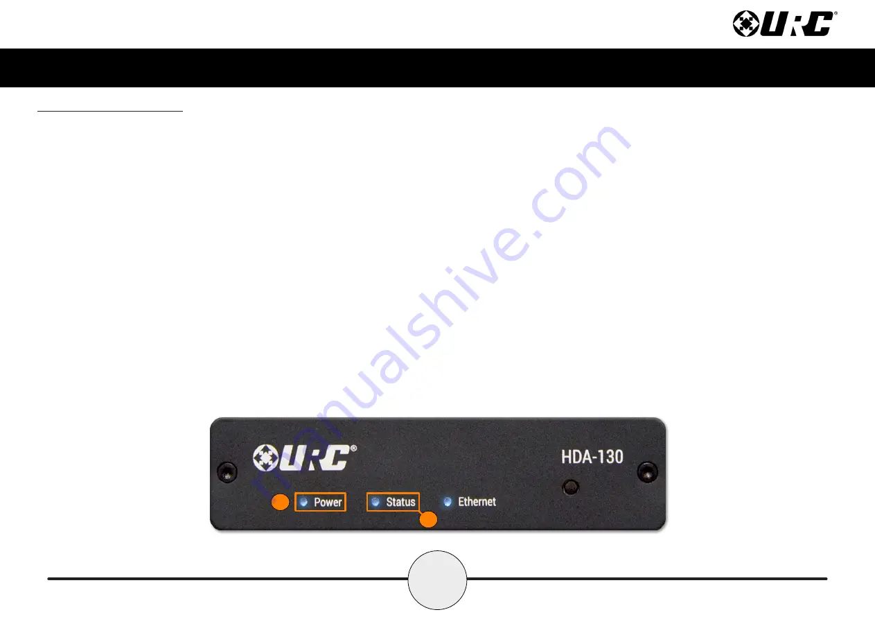
Front Panel Descriptions

There are three (3) LEDs on the front panel of the HDA-130:

1. Power LED:

Indicates one (1) of the following:

Solid Blue:

Power has been applied to the device and it has

successfully initialized.

Off:

Power has been removed from the device.

2. Status LED:

Indicates one (1) of the following:

Solid Blue:

The device has been programmed with Total Control software

and is ready for operation.

Blinking Blue:

The device is receiving a download from the Total Control

programming software.

Blinking Green:

The device is receiving a firmware upgrade, this light

continues to blink until the update is fully applied.

Off:

The device has not been programmed with Total Control software.

2

1

Summary of Contents for Total Control HDA-130

Page 1: ...HDA 130 Owner s Manual Total Control HDA 130 Owner s Manual ...

Page 2: ... Statement 15 Warning 15 FCC Caution 15 Limited Warranty Statement 16 End User Agreement 18 T able of Contents Congratulations The HDA 130 Single Zone Amplifier is URC s powerful and discrete amplifier This document highlights product features LED status conditions basic installation and general speaker wiring instructions For questions on how this device operates contact your certified URC Integr...

Page 3: ...resolution audio stream over the network Source Sharing Any zone controlled via an HDA amplifier or I O device has access to the system s HDA Audio Streams Flexible Zone Linking Link one or more zones on the fly via Total Control s Rooms Menu or have your programmer configure a Party Mode button Room Linking is an easy way to distribute audio across the system Preamplifier Output for Subwoofer Con...

Page 4: ...2 Total Control HDA 130 Owner s Manual Parts Pieces Included with the HDA 130 is the following ...

Page 5: ...has been removed from the device 2 Status LED Indicates one 1 of the following Solid Blue The device has been programmed with Total Control software and is ready for operation Blinking Blue The device is receiving a download from the Total Control programming software Blinking Green The device is receiving a firmware upgrade this light continues to blink until the update is fully applied Off The d...

Page 6: ...the local network however it has not received an IP address Off The device is not connected to the local network 4 Reset Button There are two 2 ways to press this button Single Press Tap the Reset button to power cycle the device Factory Reset Press n hold the Reset button for 10 seconds or more This option cannot be reversed once the device has been factory defaulted it requires re programming 3 ...

Page 7: ...e used simultaneously to provide two 2 HDA high definition audio streams Analog With supplied 3 5 mm adapter PCM Toslink Optical 4 Sub Out Standard RCA connector signal is left right full range 5 Speaker Output Terminal block phoenix style connector that can be configured one of the following ways Powered by External 48V DC Adapter supplied Output power of the amplifier is 2 x 30W RMS per channel ...

Page 8: ...ll or secure vertical surface 1 Insert the supplied screws into the two 2 keyed slots on the L shaped bracket as displayed on the image at the right This L shaped bracket can be pre installed and the HDA 130 amplifier can be inserted afterwards 2 Insert the supplied screws into the four 4 keyed slots for wall mounting Keyhole Diameter 0 48 12 5mm 1 2 ...

Page 9: ...7 Total Control HDA 130 Owner s Manual 3 Assure that all screws have been installed securely 3 ...

Page 10: ...2 Loosen the integrated slotted style screws turn counter clockwise and remove the phoenix connector from the terminal block on the HDA 130 3 Secure the speaker wire into the phoenix connector using the integrated slotted styled screws and reinsert it into the terminal block 4 Using the integrated slotted styled screws on the left and right sides of the phoenix connector image at the right secure ...

Page 11: ...to the network then connect the ethernet cable to an available LAN port on the local router Luxul preferred 2 Connect the ethernet cable from the previous step to any available LAN port on the HDA SW5 3 Connect another ethernet cable to an available LAN port on the HDA SW5 Network Switch 4 Connect the ethernet cable from the previous step to the ethernet port found at the rear of the HDA 130 page ...

Page 12: ...m any URC interface For specific instructions on how to use these HDA modules please refer to the HDA User s Guide The following modules are supported by the HDA 130 Multi Zone Amplifier Room Volume Module Room Zone EQ Module Volume Mixer Module Announcement Module Input Status Amplifier Status Zone Status Room Zone Status Amplifier Status Amplifier Status Room Zone EQ Announcements Not all HDA mo...

Page 13: ...required for Coaxial Digital input 1 x PCM TOSLink Digital input Zone Speaker Outputs One 1 stereo amplifier output channel Single L left R right preamplifier output for subwoofer application Rate Wattage Per Channel 30W RMS per channel 8Ω 70W Peak Power Output per channel Height x Width x Depth 1 x 4 5 x 5 Weight 12 oz ...

Page 14: ...etric EQ Permanent Zone Grouping also between multiple amplifiers 96 kHz 24 bit streaming Ducking input capability Page event support Store up to 10 WAV files in each amplifier for doorbell ring and or trigger alert chimes Thermal Operating Temperature 32 F to 86 F Humidity Maximum 95 Storage 40 F to 140 F Power AC Main Power Universal mains 100 240VAC 50 60 Hz Power Consumption 48 V DC 1 25A supp...

Page 15: ...titute a risk of electric shock to persons The exclamation point within an equilateral triangle is intended to alert the user to the presence of important operating and maintenance servicing instructions in the literature accompanying the appliance TO REDUCE THE RISK OF FIRE OR ELECTRIC SHOCK DO NOT EXPOSE THIS APPLIANCE TO RAIN OR MOISTURE To prevent electrical shock match wide blade of plug to w...

Page 16: ...e attachments accessories specified by the manufacturer Protect the power cord from being walked on or pinched particularly at plugs convenience receptacles and the point where they exit from the apparatus Use ONLY with the cart stand tripod bracket or table specified by the manufacturer or sold with the apparatus When a cart is used use caution when moving the cart apparatus combination to avoid ...

Page 17: ...ng the equipment off and on the user is encouraged to try to correct the interference by one more of the following measures Reorient or relocate the receiving antenna Increase the separation between the equipment and receiver Connect the equipment into an outlet on a circuit different from that to which the receiver is connected Consult the dealer or an experienced radio TV technician for help War...

Page 18: ...ference caused by electronic computing devices and to the extent that the URC equipment and or the URC software fails to so comply URC shall at its own expense take all reasonable measures to promptly cause such to comply THIS LIMITED WARRANTY DOES NOT COVER TECHNICAL ASSISTANCE FOR HARDWARE OR SOFTWARE USAGE EXCEPT AS EXPRESSLY PROVIDED FOR HEREIN CERTAIN IMPLIED WARRANTIES INCLUDING AN IMPLIED W...

Page 19: ...son including but not limited to product issues due to commercial use acts of God third party installation misuse limitations of technology or modification of or to any part of the URC equipment This limited warranty does not cover the URC equipment sold as used as is refurbished so called B stock or consumables such as batteries This limited warranty is invalid if the factory applied serial numbe...

Page 20: ...TIAL DAMAGES OR ALLOW LIMITATIONS ON HOW LONG AN IMPLIED WARRANTY LASTS SO THE ABOVE LIMITATIONS OR EXCLUSIONS MAY NOT APPLY TO END USER THIS LIMITED WARRANTY GIVES END USER SPECIFIC LEGAL RIGHTS AND END USER MAY HAVE OTHER RIGHTS WHICH VARY FROM STATE TO STATE OR JURISDICTION TO JURISDICTION End User Agreement The terms and conditions of the End User Agreement are available at https www urc autom...

Reviews: