background image

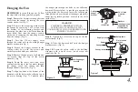
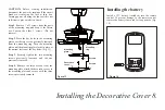
9. Operating Your Transmitter

Figure 16

Figure 15

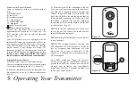
b) From the back of the transmitter, with the 

fan’s power off, restore power to the fan. Press 

and hold “SET” button for about 5 seconds and 

release. If optional light kit is installed, the 

light kit will flash twice and the signal light on 

the hand held transmitter will come on when 

the button is pressed. The fan has completed 

the pairing process with the remote control and 

is ready for use. (Fig. 16)

NOTE:

 If the self calibration test failed, turn 

the AC power off; restore power and process 

the self calibration test again.

NOTE:

 During self calibration test, the remote 

is non-fuctional.

NOTE:

 The learning frequency function and 

self calibration test will continue to retain the 

last set frequency and calibration set even 

when the AC power is shut off. If the 

frequency is changed the self calibration test 

will occur again.

Over 80W protection: When the receiver 

detects motor power consumption which is 

greater than 80W, the receiver power will be 

stopped and operation will immediately 

discontinue. Wait for 5 seconds and then turn 

the receiver power back on.

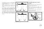
Remote Control Button Definitions:

These six buttons are used to set the fan speed as 

follows:   

I = minimum speed

II = low speed

III = medium low speed

IV = medium speed

V = medium high speed

VI = high speed

      button: Turns the fan off.

      button: Controls fan direction.

"D" and "ON" dip switch: The "D" selection is the 

light dimmable selection for LED light only. The 

"ON" selection is the light on only (no dimmable 

function). (Fig. 16)

Your DC brushless motor is equipped with an 

automatically learned type remote control. There are 

no frequency switches on the receiver; the receiver 

unit will automatically scan the frequency from the 

remote control if any changes are made. The 

frequency settings on the transmitter should be 

changed 

ONLY in case of interference or if a 

second or more ceiling fans with the same type of 
control system are installed in the same structure.


Setting the Remote Control

Follow the below steps to set the remote control:

The auto learning function will only mandate within 

60 seconds when turning the fan’s AC power ON.

a) Select desired frequency from the transmitter. The 

dip switches can be set to 16 different combinations. 

(Fig. 16)

ON ECE

1 2 3 4

ON ECE

1 2 3 4

Summary of Contents for UHP9130

Page 1: ...Ceiling Fan Installation Manual UHP9130 UHP9131 UHP9132 ...

Page 2: ...Table of Contents Safety Rules Unpacking Your Fan Installing Your Fan Installing the Decorative Cover Operating Your Transmitter Care of Your Fan Troubleshooting Specifications 1 2 3 8 9 11 12 13 ...

Page 3: ...r making electrical connections spliced conductors should be turned upward and pushed carefully up into the outlet box The wires should be spread apart with the grounded conductor and the equipment grounding conductor on one side of the outlet box and ungrounded conductor on the other side of the outlet box All set screws must be checked and retightened where necessary before installation Suitable...

Page 4: ...rews 19 rubber washers b Blade arms attachment hardware 13 screws with lock washers c Mounting hardware Wire nuts 3 1 Fan blades 6 2 Canopy assembly 3 Ball downrod assembly 4 Fan motor assembly 5 Set of blade brackets 6 6 Mounting plate 7 Decorative cover 8 Transmitter incl holder 2 mounting screws 9 12V battery 10 Balancing kit 3 1 2 6 8 7 4 5 11 a b 9 10 c ...

Page 5: ...utlet box Outlet box Outlet box Note You may need a longer downrod to maintain proper blade clearance when installing on a steep sloped ceiling To hang your fan where there is an existing fixture but no ceiling joist you may need an installation hanger bar as shown in Figure 4 3 Installing Your Fan WARNING TO REDUCE THE RISK OF FIRE ELECTRIC SHOCK OR OTHER PERSONAL INJURY MOUNT FAN ONLY TO AN OUTL...

Page 6: ...anopy and then through the ball downrod Fig 7 Step 7 Align the holes at the bottom of the downrod with the holes in the collar on top of the motor housing Fig 7 Carefully insert the hanger pin through the holes in the collar and downrod Be careful not to jam the pin against the wiring inside the downrod Insert the locking pin through the hole near the end of the hanger pin until it snaps into its ...

Page 7: ... to the WHITE wire marked AC in N from the motor Fig 9 Step 2 Connect the BLACK wire Hot from the outlet box to the BLACK wire marked AC in L from the motor Fig 9 Secure all wire connections with the plastic wire nuts provided Figure 9 Outlet Box Black AC IN L White AC IN N White Neutral Black Hot Green or bare copper ground Ground green Connect to ground wire on hanger bracket if no house ground ...

Page 8: ...tep 1 Attach the blades to the blade arms using three screws and rubber washers as shown in Figure 11 Start a screw into the blade arm do not tighten Repeat for the 2 remaining screws and washers Step 2 Tighten each screw securely starting with the center screw Make sure the blade is straight Step 3 Fasten the blade assembly to the motor using the motor screws provided Step 4 Repeat these steps fo...

Page 9: ...s distance as shown in Figure 12 Rotate the fan until the next blade is positioned for measurement Repeat for each blade The distance deviation should be equal within 1 8 3 Use the enclosed Blade Balancing Kit if the blade wobble is still noticeable 4 If the blade wobble is still noticeable interchanging two adjacent side by side blades can redistribute the weight and possibly result in smoother o...

Page 10: ...ned from the mounting ring Turn the mounting plate until the mounting plate locks in place at the narrow section of the key holes Fig 13 Step 3 Securely tighten the two mounting screws previously loosened and the one previously removed Step 4 Remove the three screws from the mounting plate attach the decorative cover to the mounting plate and secure with the three screws previously removed Figure ...

Page 11: ...discontinue Wait for 5 seconds and then turn the receiver power back on Remote Control Button Definitions These six buttons are used to set the fan speed as follows I minimum speed II low speed III medium low speed IV medium speed V medium high speed VI high speed button Turns the fan off button Controls fan direction D and ON dip switch The D selection is the light dimmable selection for LED ligh...

Page 12: ...g your comfort Cool weather Reverse An upward airflow moves warm air off the ceiling area as shown in Fig 18 This allows you to set your heating unit on a cooler setting without affecting your comfort Figure 17 Figure 18 10 Step 1 Remove the remote control holder cover from the remote control holder Step 2 Attach the remote control holder with the two remote control holder mounting screw provided ...

Page 13: ...y to help maintain its new appearance over the years Use only a soft brush or lint free cloth to avoid scratching the finish The plating is sealed with a lacquer to minimize discoloration or tarnishing Do not use water when cleaning This could damage the motor or possibly cause an electrical shock 3 There is no need to oil your fan The motor has permanently lubricated bearings IMPORTANT MAKE SURE ...

Page 14: ...using CAUTION Make sure main power is off 4 Allow a 24 hour breaking in period Most noise associated with a new fan disappear during this time 5 If using an optional light kit make sure the screws securing the glassware are tight Check that light bulb is also secure 6 Make sure the upper canopy is a short distance from the ceiling It should not touch the ceiling 1 Turn the AC power off to fan and ...

Page 15: ...an Size Speed Volts Amps Watts RPM CFM N W G W C F 96 Low High 120 120 These are approximate measures They do not include Amps and Wattage used by the light kit 31 97 lbs 39 46 lbs 0 067 0 64 3 18 48 26 28 81 5091 61 14482 38 ...

Reviews: