Installation Guide
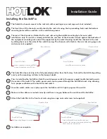
The SwitchFix channels mount to the rack rails with mounting screws and cage nuts (not included).
1
Installing the SwitchFix
The front face of the channels are attached to the rack rails using the top mounting holes and the bottom
mounting holes will be used later in the installation process.
2
The rear of the channel is attached to the rack rails using the middle mounting hole for new switch
installations only. If a switch is already installed, the rear face of the channels sit flush against the backside of
the equipment mounting rails and will be supported by the switch housing. Install the channels to the rack
by sliding them over the sides of the switch housing. The channels will attach to the rear rails using cage nuts
and screws (not supplied).
3
Attach channels to rails using 10x32
screws in middle and top RU slots.
SwitchFix inserted into channels
The SwitchFix does not ship in the fully extended position from the factory. Extend the SwitchFix by pulling
evenly on the mounting rail tabs to the deepest depth.
4
Prior to installing the SwitchFix attach the switch power cords to the power supply handle located towards
the center of the switch. The switch power cords can be passed through the SwitchFix brush strip allowing
for a proper seal between the SwitchFix and switch.
5
Once the switch cables are in place push the SwitchFix until it’s tight up against the switch.
6
Make sure the cables are routed correctly and there is no gap between the switch and the SwitchFix.
7
Attach the SwitchFix to the front rack rails using two cage nuts and screws (not supplied).
8
Installation is complete.
9
Pull mounting flanges to extend.
Slide the SwitchFix into the channels and
mount to the equipment mounting rails using
10x32 screws (not provided).
Rear/Hot Aisle
Rear/Hot Aisle
Front/Cold Aisle
Front/Cold Aisle
Rear/Hot Aisle
Rear/Hot Aisle
Front/Cold Aisle
Front/Cold Aisle


