background image


25 

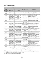
Faults 

Possible cause 

Solution 

Fault/ 
Warning 
code 

Fault icon 

Alarm 

F16 

On 

constantly 

Beep 

continuously 

INV negpower 

Please contact the distributor 
or Service center. 

F17 

On 

constantly 

Beep 

continuously 

R inv negpower 

Please contact the distributor 
or Service center. 

F18 

On 

constantly 

Beep 

continuously 

S inv negpower 

Please contact the distributor 
or Service center. 

F19 

On 

constantly 

Beep 

continuously 

T inv negpower 

Please check parallel line 
connect or not. 

F21 

On 

constantly 

Beep 

continuously 

Inv React Power 

Please contact the distributor 
or Service center. 

F22 

On 

constantly 

Beep 

continuously 

Overload Fault 

Please contact the distributor 
or Service center. 

F23 

On 

constantly 

Beep 

continuously 

Inv over 

temperature 

Please contact the distributor 
or Service center. 

F24 

On 

constantly 

Beep 

continuously 

Inv relay open 

Please contact the distributor 
or Service center. 

F25 

On 

constantly 

Beep 

continuously 

Inv relay stick 

Please contact the distributor 
or Service center. 

F27 

On 

constantly 

Beep 

continuously 

Converter Over 

Temperature 

Maybe the fan out of work 
or the environment temp. is 
to high. 

F32 

On 

constantly 

Beep 

continuously 

Communication 

line loss 

Check the parallel line is 
connect OK. 

F34 

On 

constantly 

Beep 

continuously 

Can fault 

Please contact the distributor 
or Service center. 

F35 

On 

constantly 

Beep 

continuously 

Syn line fault 

Please contact the distributor 
or Service center. 

F55 

On 

constantly 

Beep 

continuously 

Ntc abnormal 

Please contact the distributor 
or Service center. 

F56 

On 

constantly 

Beep 

continuously 

Para line loss 

Please contact the distributor 
or Service center. 

F57 

On 

constantly 

Beep 

continuously 

Bat abnormal 

Check the battery number or 
voltage is right. 


Summary of Contents for 33Q 10K

Page 1: ...User Manual High Frequency Online UPS Queen Star Series 3 Phase 10K 40KVA ...

Page 2: ...UPS to have the longest service life This manual also accounts the UPS work principle and relative functions Please obey the instructions and notes stated in this manual Keep this manual in a safe place consult it before operation Note The company reserves the right to make changes to product described in this manual at any time and without notice for reason of improvement ...

Page 3: ...nal battery 9 4 Parallel operation 10 13 4 1 Brief introduction of the redundancy 10 4 2 Parallel installation 10 4 3 Operation and maintenance 11 13 5 Operation introduce 14 19 5 1 Operation Display Panel 14 5 2 Operation Mode 15 19 5 3 Setting the output voltage and frequency 19 6 Communication 20 21 6 1 RS232 communication 20 6 2 AS400 card communication 20 21 7 Battery 22 23 7 1 Battery mainte...

Page 4: ... or do damage to the battery for the liquid spilled from battery is strongly poisonous and do harm to body 3 Please avoid short circuit between battery anode and cathode otherwise this will cause electric shock or fire 4 Don t dismantle the UPS cover there is danger of electric shock 5 Don t touch batteries Batteries are not isolated with the input circuit there is high voltage between the battery...

Page 5: ...ith them and understand their meanings Notation and Explanation Notation Explanation Notation Explanation Alert you to pay special attention Protective ground Caution of high voltage Alarm silence Turn on the UPS Overload indication Turn off the UPS Battery check Idle or shut down the UPS Recyclable Alternating current source AC Do not dispose with ordinary trash Direct current source DC Battery ...

Page 6: ...he basic equipments in some areas as finance communication government traffic manufacture education and so on This manual is applicable to the following models Type Model Input Battery Standard 10KVA 33 10K Three phase N PE Inbuilt 20KVA 33 20K Three phase N PE Inbuilt Long back up time 10KVAL 33 10KL Three phase N PE External battery bank 20KVAL 33 20KL Three phase N PE External battery bank 30KV...

Page 7: ...nment adaptability system stability is higher and to reduce the failure rate of the system and the machine efficiency is higher than 93 more energy conservation and environmental protection Intelligent monitor function A local monitor software CD is configured for 33Q 10KL 40KL UPS UPS is monitored through RS232 wire conveniently Remote monitor is feasible when SNMP card or RS485 convert card is c...

Page 8: ... 2 SNMP card 2 SNMP card 3 Parallel board install position 3 Parallel board install position 4 RS232 communication interface 4 RS232 communication interface 5 FAN 5 FAN 6 RJ45 6 RJ45 7 Input breaker 7 Input breaker 8 Wiring installation 8 Battery connect position 9 Terminal block 9 Wiring installation 10 Terminal block 11 Wheel 3 Installation ...

Page 9: ... turn on the unit and notify the carrier and dealer immediately if there is any damage or lacking of some parts 4 To unpacking the top of the plate structures in the whole machine packaging wood base the machine can be launched along the slope the diagram below 3 2 Installation notes 1 Consider the convenience of operation and maintain the space in front and back of the cabinet should be 100cm and...

Page 10: ...ccordance with the local electric code and the following instructions by professional personnel For safety please cut off the mains power breaker before installation The battery breaker also needs to be cut off if it is a long backup time model 1 Open the terminal block cover located on the rear panel of the UPS please refer to the appearance diagram 2 The input and output wires connect to the UPS...

Page 11: ...S please turn off all the loads first then perform the connection and finally turn on the loads one by one 7 No matter the UPS is connected to the utility power or not the output of the UPS may have electricity The parts inside the unit may still have hazardous voltage after turning off the UPS To make the UPS have no output power off the UPS and then disconnect the utility power supply 8 Suggest ...

Page 12: ...ncounter the hazardous of electric shock A DC breaker must be connected between the battery pack and the UPS The capacity of breaker must be not less than the data specified in the general specification as follow Model 33Q 10KL 33Q 20KL 33Q 30KL 33Q 40KL Battery voltage 192VDC 240VDC 384VDC 384VDC Battery current 55 5A 89A 83A 111A Set the battery pack breaker in OFF position and connect the 16 20...

Page 13: ...iate to be less than 3 m 2 Strictly follow the stand alone wiring requirement to perform the input wiring of each UPS 3 Connect the output wires of each UPS to an output breaker panel first and then connect the wiring to the load via the breaker panel 4 The parallel UPS must be equipped with battery individually 5 Please refer the figure followed to see the wiring of parallel operation The capacit...

Page 14: ...transfer to INV mode simultaneously as they start up sequentially in utility power mode 3 Shutdown the units shut down sequentially in INV mode When the last one completes the shutdown action each unit will shut down the inverter simultaneously and transfer to bypass mode 4 To perform the maintenance follow the stand alone requirement ...

Page 15: ...12 33Q 10KL Parallel Installation Wiring Diagram ...

Page 16: ...13 33Q 10K 33 20K L 33 30KL 33 40KL Parallel Installation Wiring Diagram ...

Page 17: ...eps twice can start the battery self diagnosis Silence function in battery bypass mode In battery bypass mode when the buzzer beeps pressing and holding the function button for more than 5 seconds buzzer beeps two times can silence the buzzer Press the button for more than 5 seconds buzzer beeps twice again to resume the alarm function LCD display screen switch Pressing the function button for mor...

Page 18: ... in the normal mode the display of main page on the front panel is shown as the figure 5 2 The utility power indicator and the Inverter indicator are turn on Load information area shows load value and the battery level area indicates dynamically when the battery is not full charged the battery level icons lit one after another circularly When the battery is full charged all the level icons are tur...

Page 19: ...eps Activate the power generator and wait until the operation is stable before connecting the output of the power generator to the UPS be sure that the UPS is in idle mode Then turn on the UPS according to the startup procedure After the UPS is turned on the loads are connected one by one It recommended that the capacity of the AC generator chosen should double that of the UPS 5 2 2 Battery Mode W...

Page 20: ...e turned on in accordance with the load capacity connected Load information area shows load value and the battery level area indicates dynamically when the battery is not full charged the battery level icons lit one after another circularly When the battery is full charged all the level icons are turn on 1 When operating in bypass mode the UPS beeps every 2 minutes If the Function key is pressed f...

Page 21: ... In the event of an UPS fault UPS enters fault operation mode at this point the fault icon turn on consistently the buzzer beeps continuously and the data information area shows current fault code refer to Appendix the display on the front panel is shown as the figure 5 5 Figure 5 5 Fault display When a warning occurred the fault icon blinks every second and users can switch to the alarm display p...

Page 22: ...f not press the F more than one second then release the output setting is enabled at this point you can start to set output voltage 4 Release the OFF key after you press it more than one second LCD display the selected output voltage in turn 5 Repeat the fourth step until the LCD indicator meets the required voltage 6 Press ON key about one second the output voltage setting completed 7 The frequen...

Page 23: ...ort is applicable to communicate with computer Description and pin assignment of RS232 Baud rate 2400bps Data bit 8 bit Ending bit 1bit Parity bit None DB 9 pin assignment RS232 Interface Pin number Function description I O 3 Rxd Input 2 Txd Output 5 GND Ground 6 2 AS400 card communication User enables to monitor and manage the UPS through installed the AS400 card optional PIN1 UPS failure normall...

Page 24: ...21 AS400 Interface ...

Page 25: ...he same number and same type of batteries 5 Keep the ambient temperature between 15 and 25 6 Do not replace the battery individually All the batteries should be replaced at the same time following the instructions of the battery supplier 7 Normally the batteries should be charged and discharged once every 4 to 6 months Charging should begin after the UPS shuts down automatically in the course of d...

Page 26: ...e UPS are still connected with the batteries and there are potential hazardous voltages Therefore before any maintenance and repairs work is carried out switch off the breaker of the battery pack or disconnect the jumper wire of connecting between the batteries 8 Batteries contain hazardous voltage and current Battery maintenance such as the battery replacement must be carried out by qualified per...

Page 27: ...act the distributor or Service center F07 On constantly Beep continuously INV over voltage fault Please contact the distributor or Service center F08 On constantly Beep continuously INV low voltage fault Please contact the distributor or Service center F09 On constantly Beep continuously R S INV short Turn off the UPS Remove all loads Ensure that the loads are not failed or the UPS has no internal...

Page 28: ...distributor or Service center F24 On constantly Beep continuously Inv relay open Please contact the distributor or Service center F25 On constantly Beep continuously Inv relay stick Please contact the distributor or Service center F27 On constantly Beep continuously Converter Over Temperature Maybe the fan out of work or the environment temp is to high F32 On constantly Beep continuously Communica...

Page 29: ...ill be cut off please switch to the backup power A12 Blink once every second Beep continuously Battery overcharging Please contact the distributor or Service center A14 Blink once every second Beep two sounds every second Overload pre warning Reduce the member of loads connected to the UPS A15 Blink once every second Beep continuously Overload fault Reduce the member of loads connected to the UPS ...

Page 30: ...ent 15A 30A 45A 61A Factor 0 8 Frequency Line mode 1 synchronized 46 54Hz 2 50Hz line 40 46 or 54 60Hz Bat mode 50Hz Distortion THD 3 R full load Overload capacity 105 125 transfers to bypass mode after 1 minutes 125 5 load 150 5 transfers to bypass mode after 30second Current crest ratio 3 1 Efficiency Line 93 Bat 90 Rated bat No 192VDC 240VDC 384VDC Charge current 1A 7 5A 1A 6A 5 5A ECO EPO Opti...

Page 31: ...installed or used in a place where the altitude is above than 1000m the output power must be decrease in use please refer to the table Altitude M 1000 1500 2000 2500 3000 3500 4000 4500 5000 Load 100 95 91 86 82 78 74 70 67 ...

Reviews: