


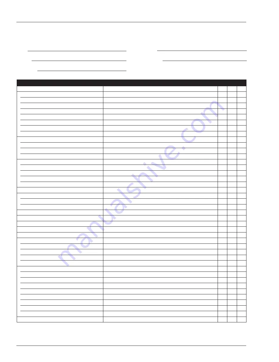
Daily Preventative Maintenance Checklist
16
SB66JRT – 0084221
ITEM
INSPECTION OR SERVICES
Y
N
R
Operator’s Manual
In place, all pages readable and intact
Engine
Oil level
Between full and add marks
Coolant
Air intake and fan free of obstructions, belt in good condition
Radiator
Cap tight, good condition and clean
Fuel tank and line
Tank full, cap in place and tight/ no leaks
Air filter
Clear indicator
Charging system
Proper operation
Cold weather start kit
No damage or deformation
Electrical System
Emergency power battery
Condition and charged for proper operation
Battery fluid level and terminals
Proper level/clean, connectors tight
Cables and wiring harness
No wear or physical damage
Hydraulic System
Fluid level
Between full and add marks
Fluid filter
Verify operation in the green zone
Hose, tubes and fittings
No leaks
Cold weather warm-up kit
Proper operation
Foam Filled Tires and Wheels
Good condition
Lower Control Station
Operating controls
Proper operation
Emergency stop and emergency power
Shuts off lower controls/proper operation
Emergency Lowering
Proper operation
Level Sensor
Sounds tilt alarm
Flashing Light
Proper operation
Sandblast Protection Kit
In place and proper operation
Bumpguard
In place, no damage or deformation
Structures
Weldments
Welds intact, no damage or deformation
Slide pads
In place, no damage or deformation
Fasteners
In place and tight.
Wire ropes
No deformation or broken strands
Upper Control Station
Guardrail system and lanyard anchors
Welds intact, no damage or deformation
Operating controls
Proper operation
Emergency stop and emergency power
Shuts off upper controls/proper operation
Horn
Sounds when activated.
Electrical power outlet
Proper operation of outlet
Drive motion alarm
Sounds when aerial platform moves
Driving and work lights
Proper operation
Platform control cover
In place and proper operation
Placards and Decals
In place and readable
Maintenance Table Key: Y = Yes/Acceptable, N = No/Not Accetable, R = Repaired/Acceptable
Daily Preventative Maintenance Checklist
Preventative Maintenance Report
Date:
Owner:
Model No:
Serial No:
Serviced By:
Summary of Contents for SB66JRT
Page 2: ......
Page 19: ...Decal Location SB66JRT 0084221 17 Decal Location A08065S ...
Page 23: ......


