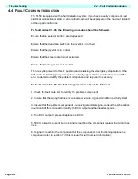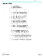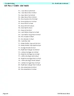
Page 3-26
Maintenance
3.18 - Electric Motor
TL50 Service & Parts
3.18 E
LECTRIC
M
OTOR
T
ROUBLESHOOTING
1. Read the nameplate to become familiar with the motor, especially the rated voltage.
2. Try to turn the shaft by hand. Keep motor leads separated while doing this. If the shaft turns
freely, go to step 3. If the shaft won’t turn, proceed to step A.
a. The shaft could be tight for a number of reasons, this check is to determine if
the tightness is of a temporary nature only. Obtain power to produce the
nameplate voltage. Do not make a permanent connection. First touch the
motor leads quickly to the power supply just long enough to observe if the
shaft runs. If it does turn, then hold the motor leads on the power supply for a
longer time.If the motor sounds normal, go to step 3. If the motor sounds
noisy, it should be taken apart as described in the disassembly section.
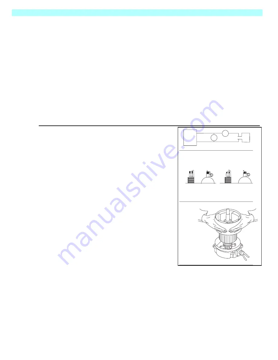
3. If the motor turned freely, connect an ammeter in the circuit as shown in Figure 3-9A. With
rated voltage applied and the shaft running free, the ammeter should read less than 20% of
the nameplate full load current. If the motor meets the above conditions, then it can be
assumed the original problem is external to the motor.
Figure 3-9: Electric Motor
D
ISASSEMBLY
NOTE:
Do not place the stator ring in any mechanical
holding device during the disassembly or assembly
operation. Permanent distortion or other damage will
result.
1. Remove three bolts.
2. Remove pulley end cover.
3. Pull the armature out of the assembly in one
swift motion.
4. Remove commutator end cover.
I
NSPECTION
1. Once the motor has been disassembled, go
through the following check list steps to deter-
mine where the problem lies.
2. Bearings should spin smoothly and easily and
have ample lubrication and be free of corrosion.
3. Armature should be checked for grounds and
shorted turns. Refinish commutator surface if
pitted or excessively worn.
4. Brushes should be checked for wear and to
ensure that they are free in the brush holders.
DC
Power
Supply
V
A
Voltage Meter
Ammeter
Brushes and
springs in their
final position
Brushes raised with
the springs in locked
position on the side
of the brush
A
B
C
Keep fingers
clear of this
space.
DC
Motor
Summary of Contents for 503502-000
Page 1: ...ERVICE PARTS MANUAL POWERED ACCESS WORK PLATFORM TL50...
Page 21: ...Page 16 TL50 Service Parts Specifications Notes...
Page 51: ...Page 3 30 Maintenance 3 19 Torque Specifications TL50 Service Parts NOTES...
Page 59: ...Page 5 2 Schematics 5 1 Introduction TL50 Service Parts...
Page 60: ...Page 5 3 Schematics 5 1 Introduction TL50 Service Parts...
Page 61: ...Page 5 4 Schematics 5 1 Introduction TL50 Service Parts...
Page 62: ...Page 5 5 Schematics 5 1 Introduction TL50 Service Parts...
Page 63: ...Page 5 6 Schematics 5 1 Introduction TL50 Service Parts Notes...
Page 66: ...Page 6 3 Illustrated Parts Breakdown General Assembly TL50 Service Parts 1 1 2 3 4 5 6 7...
Page 70: ...Page 6 7 Illustrated Parts Breakdown Booms Posts Assembly TL50 Service Parts 44 45...
Page 72: ...Page 6 9 Illustrated Parts Breakdown Platform Assembly Standard TL50 Service Parts...
Page 74: ...Page 6 11 Illustrated Parts Breakdown Platform Assembly Rotator TL50 Service Parts...
Page 88: ...Page 6 25 Illustrated Parts Breakdown Hydraulic Tank Assembly TL50 Service Parts...
Page 90: ...Page 6 27 Illustrated Parts Breakdown Electrical Assembly TL50 Service Parts...
Page 92: ...Page 6 29 Illustrated Parts Breakdown Hydraulic Assembly TL50 Service Parts...
Page 94: ...Page 6 31 Illustrated Parts Breakdown Decal Assembly TL50 Service Parts...
Page 95: ...Page 6 32 Illustrated Parts Breakdown Decal Assembly TL50 Service Parts...
Page 96: ...Technician s Print TL50 W ork Platform Electrical Schematic...
Page 97: ...Technician s Print TL50 W ork Platform Harness Schematic...
Page 98: ......

