


Step 3
After all components from Step 2 are in place, you may choose to
tighten the Set screws which will lock all the components togeth
-
er, and prevent them from separating or drifting.
The set screws are located at each insertion point, and marked in
this instruction book with a “ ”.
• At the back of the Base, on each post where the Extension arms
are inserted.
• At the top of each Extension arm where the Gas arms are inserted.
Use the 2.5 mm Allen wrench provided. Make sure not to over
-
tighten the set screws.
*
*
*
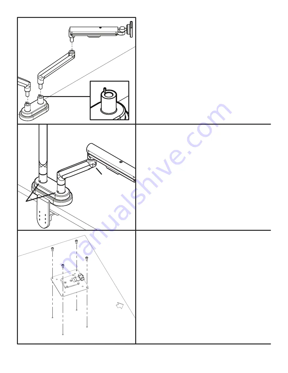
Step 2
With the Base attached to the desk, it’s time to assemble the
remainder of the arm by next inserting the Extension arms into
the Base.
Note:
The Base comes with pre-installed stopping-pins on each
post, (see fig. 4) which limits the arms rotation to 180 degrees. If
ou want a full 360 degree rotation, remove these pins with the
1.5mm Allen wrench.
Once the Extension arms are inserted, insert a Gas arm into each
Extension arm.
© UPLIFT Desk
• 1-800-349-3839 • [email protected] • upliftdesk.com
fig. 4
Step 4
Place your monitors face down on a flat surface, making sure
not to scratch the screen. Next, attach the VESA mounts to
the back of each monitor using a Phillips-head screwdriver
and four Monitor screws each. The mount is designed to fit
the industry standard VESA 75 mm & 100 mm hole patterns.
Make sure the VESA mount is securely fastened to your mon
-
itor before moving on to the next step.
Note:
make sure the tab on each VESA mount is facing the
top of each monitor.


