UPG GM9T-UP Maintenance And Service Manual Download Page 4

272434-UUM-A-0407

4

Unitary Products Group

FURNACE USER MAINTENANCE

Every time the filters are changed the following items should be visually
inspected:

Check combustion air and vent pipe for blockage or leakage.

Check all components to be sure they are in good condition and
that there are no obvious signs of deterioration.

Check the drain lines to make sure there are no cracks or leaks.

Check for dirt or lint on any surfaces or on components. Do not try
to clean any of the surfaces or components. Cleaning of the fur-
nace and its components must be done by a qualified service pro-
fessional.

If, during the inspection of your furnace, you find any of the following
conditions:

Excessive amounts of dust and lint on components.

Damaged or deteriorated components or surfaces.

Leaks or blockage in the vent pipe passages.

Water on any surface inside or outside of the furnace.

Do not operate the furnace, call a certified dealer / servicing contractor
to check and / or clean your furnace, or for more information if you have
questions about the operation of your furnace.

If all components appear to be in good operating condition, replace the
front panels. Turn ON the gas and electrical power supplies to the fur-
nace, and set thermostat to the desired temperature.

Air Filters

Dirty filters greatly restrict the flow of air and may cause damage to the
moving parts of the furnace. If the filters become clogged the heat
exchangers and blower motor could overheat resulting in a potentially
dangerous situation. The filters should be checked every 3 months. On
new construction, check the filters every week for the first four weeks
and every three weeks after that, especially if the indoor fan is running
continuously. When replacing the filter(s) you must use filters that are
the same size as those recommended in Table 1. Use the following pro-
cedure to determine the filter size. Never operate your furnace without a
suitable air filter.
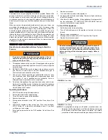
1.

Measure the furnace width and use that measurement to deter-
mine the cabinet width.

A 14-1/2” wide cabinet is a “A” cabinet.

A 17-1/2” wide cabinet is a “B” cabinet.

A 21” wide cabinet is a “C” cabinet.

A 24-1/2” wide cabinet is a “D” cabinet.

2.

Locate the cabinet size on Table 1 then determine whether you
have a bottom or side return air duct using the following method.

A.

If the return air filter is on the left or right side of the furnace it
is a side return

B.

If the air filter is on the bottom of the furnace then you have a
bottom return.

C.

If the air filters are on the bottom and the side of the furnace
then you have a bottom and side return. You must replace
both air filters. Table 1 will indicate 2 filters by using brackets
with the number two (2).

D.

If the air filters are on both sides of the furnace then you have
a two sided return. You must replace both air filters. Table 1
will indicate 2 filters by using brackets with the number two
(2).

3.

After you determine the cabinet size and what return configuration
you have, look up the recommended filter size from Table 1.

Replacing Filters

Filters used with this furnace must be installed external to the furnace
casing. DO NOT attempt to install filters inside the furnace cabinet.

Some installations may have the air filter in a rack attached to the cas-
ing of the furnace or placed in the return air duct. If the filter location or
replacement process is not obvious, contact your installer or service
technician for assistance. Replace throw away filter(s) with the same
size new filter(s). Throw away filter(s) may be replaced with cleanable
filter(s) at this time. Cleanable filter(s) may be cleaned as described in
the manufacturer instructions or as described below and then re-
installed.

* Some installations of this model require only one filter.

How to Clean your Filter

High-velocity filters may be cleaned with a vacuum cleaner or washed
with a garden hose. Be sure to shake off excess water and allow filter to
completely dry before re-installing the filter.
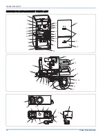
Blower Care

Even with good filters properly in place, blower wheels and motors will
become dust laden after long months of operation. The entire blower
assembly should be inspected annually. If the motor and wheel are
heavily coated with dust, they can be brushed and cleaned with a vac-
uum cleaner. If the blower cannot be properly cleaned without removing
it from the furnace, then this service must be performed by a qualified
service agency.

Before proceeding, be sure the area is well ventilated. Turn
the thermostat OFF. If the blower is running, wait until it
stops automatically. Turn OFF the gas and electrical power
supplies to the furnace. Check all metal parts and surfaces
to be sure they have cooled to room temperature before
you begin.

TABLE 1: 

Filter Sizes

Cabinet Size

Side (in)

Side (cm)

Bottom (in) Bottom (cm)

14-1/2” (A)

16 x 25

40.6 x 63.5

14 x 25

40.6 x 63.5

17-1/2” (B)

16 x 25

40.6 x 63.5

16 x 25

40.6 x 63.5

21” (C)

16 x 25

40.6 x 63.5

20 x 25

50.8 x 63.5

24-1/2” (D)

(2) 16 x 25* (2) 40.6 x 63.5*

22 x 25

55.9 x 63.5

Make sure you DO NOT move the clip on weight on the
indoor fan wheel when cleaning the wheel. This weight is
used to balance the wheel. Moving the weight will cause
the fan wheel to vibrate.

Summary of Contents for GM9T-UP

Page 1: ...at have been wet or the furnace if deemed necessary FIRE OR EXPLOSION HAZARD Failure to follow safety warnings exactly could result in serious injury death or property damage Do not store or use gasoline or other flammable vapors and liquids in the vicinity of this or any other appliance WHAT TO DO IF YOU SMELL GAS Do not try to light any appliance Do not touch any electrical switch do not use any...

Page 2: ...ce casing making sure the physical support is sound without sagging cracks or gaps Examine the furnace base making sure it is physically sound without cracks gaps or sagging and has a good seal 5 Examine the furnace casing for obvious signs of deterioration 6 Examine the burner flames to make sure they are in good adjust ment Refer to the pictorial sketch shown in Figure 2 as a compari son to the ...

Page 3: ...f the control system and any gas control which has been under water Operating Instructions 1 STOP Read the safety information above 2 Set the thermostat to the lowest setting 3 Turn off all electric power to the appliance 4 Remove burner door 5 Move gas control switch to the OFF position Do not force See Figure 4 6 Wait five 5 minutes to clear out any gas If you then smell gas STOP Follow B in the...

Page 4: ... the air filters are on the bottom and the side of the furnace then you have a bottom and side return You must replace both air filters Table 1 will indicate 2 filters by using brackets with the number two 2 D If the air filters are on both sides of the furnace then you have a two sided return You must replace both air filters Table 1 will indicate 2 filters by using brackets with the number two 2...

Page 5: ...ners should be checked periodically for dirt accumulation If cleaning is required follow this procedure 1 Turn off the electrical power to the unit 2 Turn off the gas supply at the external manual shut off valve and loosen the ground union joint 3 Remove the burner door and remove the burner box cover 4 Disconnect wires from flame sensor rollout switch and HSI igniter Remove igniter carefully as i...

Page 6: ...at Low 4 1st Stage Satisfied The Thermostat opens the circuit between R and W1 Immediately the Gas Valve is de energized and Flame Rectifica tion is lost The Inducer Motor is de energized after a 15 second Post Purge and the Hum terminal is de energized The Fan Off Delay circuit is initiated The Delay time can be field set at 60 90 120 or 180 seconds It comes from the fac tory set at 60 seconds Th...

Page 7: ... heat RAPID RED FLASH Twinning error incorrect 24V phasing Check twinning wiring RAPID AMBER FLASH Flame sense current is below 1 5 microamps Check and clean flame sensor Check for proper gas flow 4 AMBER FLASHES The control board is recieving a Y signal from the thermostat without a G signal indicating improper thermostat wir ing 1 RED FLASH This indicates that flame was sensed when there was not...

Page 8: ...a disconnected or loose wire or by a cracked or bro ken igniter STEADY ON RED Control failure Replace control board 60 MINUTE AUTOMATIC RESET FROM LOCKOUT This control includes a watchdog type circuit that will reset from a lockout condition after 60 minutes Operational faults 6 7 8 will be reset This provides protection to an unoccupied structure if a temporary condition exists causing a furnace ...

Page 9: ...NDUCER LOW STAGE PRESSURE SWITCH HSI 1ST STAGE MAIN VALVE FLAME SENSE LOW CIRCULATOR HEAT SPEED 1ST STAGE LOW PRESSURE SWITCH CLOSE RECOGNITION HSI WARM UP 17 SEC IGNITION ACTIVATION PERIOD 4 SEC TRIAL FOR IGNITION 7 SEC INTER PURGE 60 SEC HSI WARM UP 27 SEC IGNITION DEACTIVATION PERIOD 3 SEC HEAT FAN DELAY ON 30 SEC BURN TIME POST PURGE 15 SEC HEAT FAN DELAY OFF SELECTABLE 60 90 120 180 SEC OFF O...

Page 10: ... Products Group SECTION III REPLACEMENT PARTS LIST 25 37 51 26 40 13 61 62 2 60 59 55 7 28 58 16 12 11 24 69 10 39 5 29 31 45 21 46 19 20 48 50 15 53 14 1 3 23 44 2 4 17 42 24 43 22 54 8 34 27 6 29 38 41 37 30 32 9 40 36 47 18 13 ...

Page 11: ...ISCELLANEOUS 37 PLUG WINDOW CLEAR 1 5 38 CONNECTOR AIR INTAKE 2 39 TUBING SILICONE Gray 188 ID 2 ft Req d 40 TUBING PREFORMED 41 GASKET AIR INTAKE 42 GASKET COMBUSTION BLOWER 43 GASKET CONDENSATE PAN 44 GASKET UPPER CONDENSATE PAN 45 GASKET GAS CONTROLS 46 GASKET COND COIL LOWER PAN 2 Req d 47 GROMMET MANIFOLD SEAL 48 GROMMET MOTOR 3 Req d 49 GROMMET 1 2 DIA 50 FERRULE MOTOR MOUNT 3 Req d 51 HANDL...

Page 12: ...ER KIT 1 FILTER 14 1 2 CABINETS 1BR0214 BOTTOM RETURN FILTER KIT 1 4 FILTER 14 1 2 CABINETS 1BR0117 BOTTOM RETURN FILTER KIT 1 FILTER 17 1 2 CABINETS 1BR0217 BOTTOM RETURN FILTER KIT 1 4 FILTER 17 1 2 CABINETS 1BR0121 BOTTOM RETURN FILTER KIT 1 FILTER 21 CABINETS 1BR0221 BOTTOM RETURN FILTER KIT 1 4 FILTER 21 CABINETS 1BR0124 BOTTOM RETURN FILTER KIT 1 FILTER 24 1 2 CABINETS 1BR0224 BOTTOM RETURN ...

Page 13: ...272434 UUM A 0407 Unitary Products Group 13 SECTION IV WIRING DIAGRAM FIGURE 8 Wiring Diagram ...

Page 14: ...272434 UUM A 0407 14 Unitary Products Group NOTES ...

Page 15: ...272434 UUM A 0407 Unitary Products Group 15 NOTES ...

Page 16: ...es only to products installed in the United States and Canada EXCLUSIONS This warranty does not cover any 1 Shipping labor or material charges 2 Damages resulting from transportation installation or servicing 3 Damages resulting from accident abuse fire flood alteration or acts of God tampering altering defacing or removing the product serial number will serve to void this warranty 4 Damages resul...

Reviews: