background image

— 24 —

Black Mark detection error (in Black Mark mode)
When Black Mark cannot be detected even if a certain amount of paper feed
is carried out for Black mark detection, a Black Mark detection error occurs.  If
black detection continues more than the specified period, a No Paper condition
is assumed and the same error as No Paper is indicated.

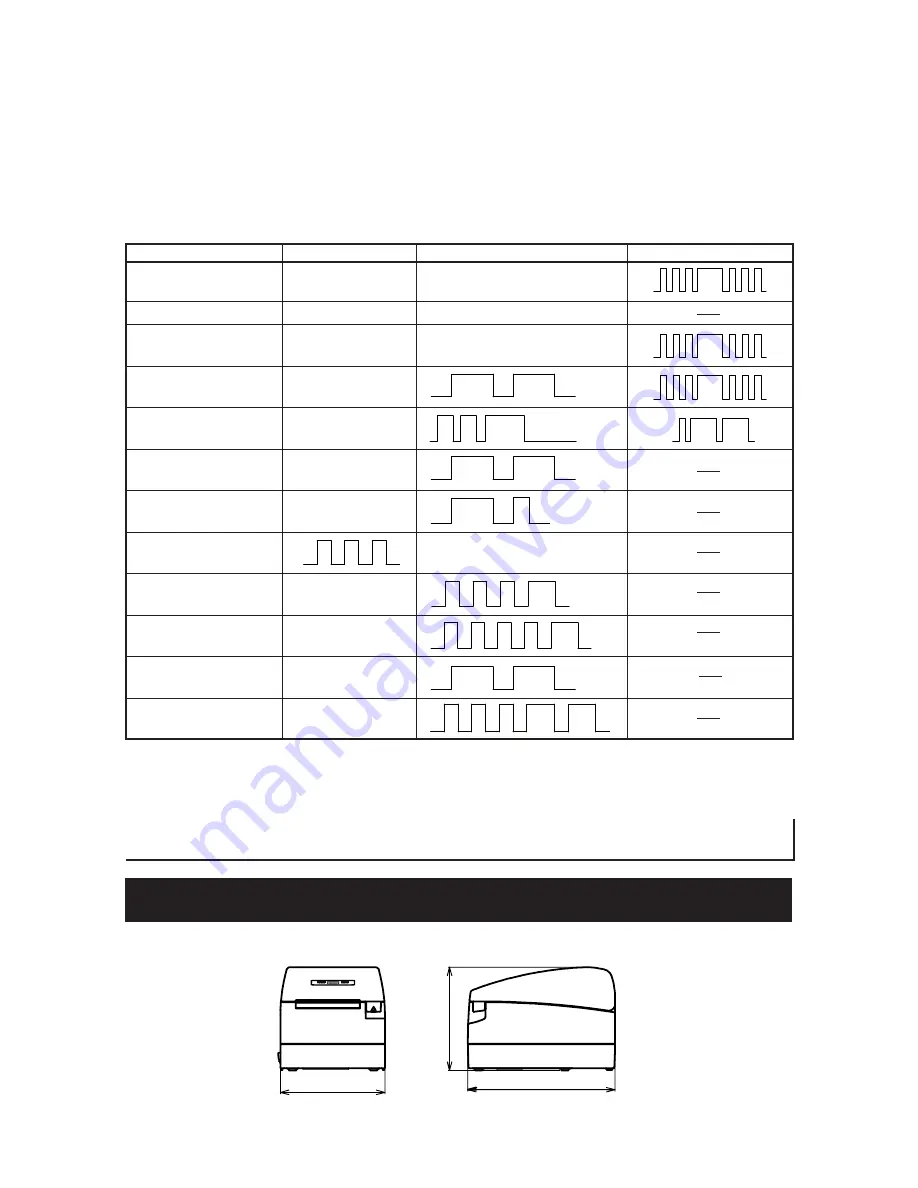
Lighting and blinking status of each error including the above is shown below.

Status

POWER LED

ERROR LED

Buzzer

Paper-end

Lights

Lights

Paper near-end

Lights

Lights

Cover open error

Lights

Lights

Cover open error *1

Lights

Cutter lock error

Lights

Head overheat error

Lights

Motor overheat error

Lights

Memory check error

Lights

Low voltage error

Lights

High voltage error

Lights

Macro execution

Lights

wait *2

Black Mark detection

Lights

error

*1: When the printer is printing.
*2: The ERROR LED may blink even in the execution of macro function.

(Unit: mm)

207

147

147

5.  OTHER

5.1  External Views and Dimensions

Summary of Contents for CT-S2000

Page 1: ...LINE THERMAL PRINTER MODEL CT S2000 CT S2000DC User s Manual Uniwell Uniwell Systems UK Ltd ...

Page 2: ...OD OHJLVODFLyQ SUHYLVWD SRU OD LUHFWLYD VREUH UHVLGXRV GH DSDUDWRV HOpFWULFRV HOHFWUyQLFRV 5 YLJHQWH QLFDPHQWH HQ OD 8QLyQ XURSHD 6H GHVLGHUDWH JHWWDUH YLD TXHVWR SURGRWWR QRQ PHVFRODWHOR DL ULILXWL JHQHULFL GL FDVD VLVWH XQ VLVWHPD GL UDFFROWD VHSDUDWR SHU L SURGRWWL HOHWWURQLFL XVDWL LQ FRQIRUPLWj DOOD OHJLVOD LRQH 5 LUHWWLYD YDOLGD VROR DOO LQWHUQR GHOO 8QLRQH XURSHD HSRQHHU GLW SURGXFW QLHW EL...

Page 3: ...ers muß nahe dem Gerät angebracht und leicht zugänglich sein For Uses in Canada This Class A digital apparatus complies with Canadian ICES 003 This digital apparatus does not exceed the class A limits for radio noise emissions from digital apparatus as set out in the radio interference regulations of the Canadian department of communications Pour L utilisateurs Canadiens Cet appareil numérique de ...

Page 4: ...to some printer models The following describes the degree of hazard and damage that could occur if the printer is improperly operated by ignoring the instructions indicated by the warning symbols This symbol is used to alert your attention to important items WARNING Neglecting precautions indicated by this symbol may result in injury or damage to properties CAUTION This symbol is used to alert you...

Page 5: ...uid over the printer A metallic foreign object if accidentally dropped into the printer may cause printer failure fire or electric shock Should it occur immediately turn the printer off unplug it from the supply outlet and call your local Citizen Systems dealer Do not handle the printer in the following ways Do not allow the printer to sustain strong impacts or hard jolts e g trampling dropping st...

Page 6: ...oise devices Avoid using the printer with a device that is a strong source of noise The printer may have an adverse effect on nearby radio or TV transmissions There may also be cases when nearby electrical appliances adversely influence the printer causing data errors or malfunction A state where this product is installed vertically or sidelong Malfunction failure or electric shock may result CAUT...

Page 7: ... circuit breaker to trip Do not allow anything to rest on the power cord Do not place the printer where the power cord will be trampled on Do not use or carry the printer with its power cord bent twisted or pulled Do not attempt to modify the power cord unnecessarily Do not lay the power cord in the neighbor of a heating device Neglecting these cautions may cause wires or insulation to break which...

Page 8: ...ith plastic adhesive tapes Avoid forcibly pulling already loaded paper by hand Avoid wedging the paper into the printer May jam paper To release refer to Removing Jammed Paper in this manual Avoid using a sharp pointed device to operate panel keys Be sure to firmly insert the cable plug into its mating socket A cross connection may damage the printer s internal electronics or the host system s har...

Page 9: ...before launching maintenance work DAILY MAINTENANCE To prevent injury and printer failures from worsening observe the following Do not touch the printing surface of the thermal head Do not touch any of the moving parts e g paper cutter gears active electrical parts while the printer is working In case of trouble do not attempt to repair the printer Ask Citizen Systems service for repair Be careful...

Page 10: ...Interface Cables 16 3 3 Connecting the Cash Drawer 17 3 4 Precautions in Installing the Printer 18 3 5 Partition for Paper Roll 18 3 6 Setting DIP Switch 19 3 7 Adjusting the Paper Near end Sensor 20 4 MAINTENANCE AND TROUBLESHOOTING 21 4 1 Setting Replacing the Paper Roll 21 4 2 Removing Jammed Paper 21 4 3 Cleaning the Print Head 22 4 4 Self printing 23 4 5 Hexadecimal Dump Printing 23 4 6 Error...

Page 11: ... Roll Capacity with ability to use 83 mm 80 mm 60 mm and 58 mm wide paper rolls Can use paper roll with a maximum of 102 mm diameter Equipped with USB interface as standard Replaceable interface board High speed parallel interface Parallel interface model Built in cash drawer interface Auto cutter mechanism provided as a standard User customization such as memory switch setting are available Page ...

Page 12: ...3 Model Classification The printer models are classified by the following designation method CT S2000DC DC power supply type AC adapter Option CT S2000 RS E BK Label Black mark No marking Standard L Label M Black mark Body case color WH Cool white BK Black GR Dark Grey Interface PA IEEE1284 USB RS RS 232C USB UB USB only Option Power supply No marking AC power type built in power supply DC DC powe...

Page 13: ...Interfacing Serial RS 232C compliant Parallel IEEE 1284 compliant USB Cash drawer interface 2 cash drawers are supported Input buffer 4k bytes 45 bytes Supply voltage DC 24 V 7 Power consumption Approx 70W in normal printing AC adapter Rated input AC 100 to 240 V 50 60 Hz 150 VA Rated output DC 24 V 2A Model 35AD1 for CT S2000 Model 35AD2 for CT S2000DC Weight CT S2000 Approx 2 kg CT S2000DC Appro...

Page 14: ...n button Power switch This switch turns the printer power ON OFF Notes 1 When paper width is 83 80 60 58 mm 2 The number of printable columns is selectable with a Memory Switch The number of columns in this table refers to typical model Printer varies partly in the number of columns depending on printer specifications 3 This rating is obtained by the use of specified AC adapter 35AD1 or 35AD2 4 As...

Page 15: ...e cause of the error POWER LED FEED button ERROR LED Interface connector Serial parallel etc Cash drawer kick out connector Power connector DC power supply type Rear Connectors Interface board mounting screws Operation Panel Interface connector Serial parallel etc Connects to the interface cable A DIP switch is provided on the serial interface board Cash drawer kick out connector Connects to the c...

Page 16: ...unctions can be stored in nonvolatile memory The functions are valid even if the printer power is turned off 2 2 Printer Cover Inside Paper feed roller Feeds paper as part of print mechanism Paper near end sensor Detects near paper end change position in accordance with the outer diameter of paper core Auto cutter Cuts the paper with a command at the end of printing Cutting method is selectable be...

Page 17: ... DO NOT pull out by the cable Always hold the plug Always keep the AC power supply away from other noise generating equipment DO NOT pull the AC power cord Otherwise fire electric shock or power disconnection may result If lightning is approaching unplug the AC power cord from the wall outlet Otherwise fire or electric shock may result Keep the power cord away from heat generating appliances Other...

Page 18: ...AUTION When disconnecting the cable always hold the connector Be careful not to insert the USB interface cable into the cash drawer kick out connector Serial Interface Parallel Interface For serial interface cable use the one with the following connection 25 pin 25 pin cable 9 pin 25 pin cable Printer Pin Signal 1 FG 2 TXD 3 RXD 4 RTS 6 DSR 7 SG 20 DTR PC Signal Pin RXD 2 TXD 3 DTR 4 SG 5 DSR 6 CT...

Page 19: ...DC 2 Driving current Approx 1A max shall not exceed 510 ms 3 DRSW signal Signal levels L 0 to 0 5 V H 3 to 5 V 3 DRSW signal DRSW signal status can be tested with the DLE EOT GS a or GS r command or at pin 34 on the parallel interface port 4 Drive Circuit printer side No Signal Function 1 FG Frame Ground 2 DRAWER 1 Drawer 1 drive signal 3 DRSW Drawer switch input 4 VDR Drawer drive power supply 5 ...

Page 20: ...roduct is installed vertically or sidelong Malfunction failure or electric shock may result CAUTION When setting the partition to the slot for 58 mm or 60 mm paper roll be sure not to set it slanted 3 5 Partition for Paper Roll At the time of shipment this partition is set to 80 mm wide roll paper position 1 Confirm that the power switch is OFF 2 Open the printer cover 3 Set the partition to each ...

Page 21: ...OT remove screws other than those for mounting the serial interface board Initial Settings 1 Communication condition DIP switch setting Memory switch OFF setting method setting 2 Hand shake XON XOFF DTR DSR OFF 3 Bit length 7 bits 8 bits OFF 4 Parity check With parity None OFF 5 Parity selection Even parity Odd parity OFF 6 ON 7 ON 8 INIT Reset Invalid OFF Selecting baud rate Switch No 6 7 2400 OF...

Page 22: ...2 φ18 2 φ25 φ22 3 φ29 φ25 4 φ34 φ32 Factory setting for USA version Factory setting for other country version CAUTION Paper remaining differs by the type of paper roll used The external diameter of the paper roll is only for reference When a paper end error is detected incorrectly during using a paper roll with a honey comb type core move the sensor position to the larger number Roll paper diamete...

Page 23: ...e cutter blade remains protruded with paper jammed do not open the printer cover forcibly Referring to section 4 4 restore the blade to the normal position and then open the cover 3 Remove the jammed paper including any paper chips remaining 4 Turn on the printer The auto cutter mechanism is initialized and the alarm is cleared CAUTION If the cutter blade remains protruded with paper jammed DO NOT...

Page 24: ...th a bare hand or metal object either Print thermal head 4 4 Self printing Insert paper into the printer With the FEED button pressed and held turn the printer power on keep the FEED button held for about 1 second and then release the FEED button The printer starts self printing The printer prints model name version DIP switch setting memory switch setting and built in fonts Memory switch setting ...

Page 25: ... 4C 4D 4E EFGHIJKLMN 4F 50 0D 0A 31 32 33 0D 0A OP 123 4 6 Error Indication Paper end Paper empty is detected in two steps paper near end and paper end It causes the ERROR LED to light If paper end is detected refill the paper If the printer cover is open a paper end is detected Printer cover open During printing do not open the printer cover If you open the printer cover accidentally the ERROR LE...

Page 26: ...each error including the above is shown below Status POWER LED ERROR LED Buzzer Paper end Lights Lights Paper near end Lights Lights Cover open error Lights Lights Cover open error 1 Lights Cutter lock error Lights Head overheat error Lights Motor overheat error Lights Memory check error Lights Low voltage error Lights High voltage error Lights Macro execution Lights wait 2 Black Mark detection Li...

Page 27: ... E2D from Nippon Paper paper roll PD150R PD160R from Ohji Paper PA220AG HP220A HP220AB 1 F230AA P220AB from Mitsubishi Paper Paper width 80 0 1 CAUTION DO NOT use the following type of paper roll Paper with folds Paper with bent corners Paper pasted or glued to the core In wound paper roll print side in Paper width 60 0 1 Maximum print area 54 5 Maximum print area 52 5 Paper width 58 0 1 Paper thi...

Page 28: ...Spool Print Invalid Valid SW2 4 Full Col Print LineFeed WaitData SW2 5 Resume aft PE Next Top SW2 6 Reserved Fixed SW2 7 Reserved Fixed SW2 8 PNE Sensor Valid Invalid Memory SW3 1 Resum Cttr Err Valid Invalid SW3 2 Reserved Fixed SW3 3 Parallel 31 Pin Valid Invalid SW3 4 Reserved Fixed SW3 5 Reserved Fixed SW3 6 Reserved Fixed SW3 7 CBM1000 Mode Invalid Valid SW3 8 Resum Open Err Close Command Mem...

Page 29: ...merica Korea Memory SW9 3 Kanji OFF ON OFF SW9 4 JIS Shift JIS JIS JIS Shift JIS Memory SW10 1 Print Density 100 70 75 80 85 90 95 100 105 110 115 120 125 130 135 140 SW10 2 Print Speed Level 9 Level 1 Level 2 Level 3 Level 4 Level 5 Level 6 Level 7 Level 8 Level 9 SW10 3 ACK Timing Before Busy Before Busy Same Period After Busy In this printer Memory Switches 9 3 and 9 4 are not usable For USA ve...

Page 30: ...ting item 5 Returning to the memory switch select mode When the setting of the desired content is completed open the printer cover and then close the printer cover This allows the printer to print the setting of the changed memory switch 6 Saving the setting and exiting the memory switch setting mode Press the FEED button short to move to Save To Memory Then press and hold the FEED button The prin...

Page 31: ...Uniwell Systems UK Ltd Uniwell Building Greenbank Technology Park Challenge Way Blackburn BB1 5US Tel 01254 503800 Fax 01254 503801 www uniwell co uk ...

Reviews: