UniVox
®
TV-200
7
● If the smallest side of the looped area is larger than 10 metres, another
loop figuration should be used, for example a figure eight or SLS
solution.
● Is the overspill outside of the loop acceptable? If not, plan for a
UniVox
®
SLS system with heavily reduced overspill.
● Plan all other electrical equipment in order not to create disturbing
magnetic fields.
● Do not put the loop wire close to a stage area to avoid feedback from
electric instruments and dynamic microphones.
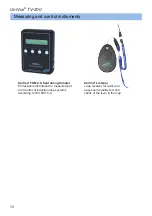
● Always measure and certify the loop installation with UniVox
®
FSM
field strength meter according to the IEC 60118-4 standard.
You can fill out a UniVox
®
Certificate for induction loops (pdf) by
downloading the form at www.edin.se, see Measuring/Control, Standard for
measurement of induction loops – IEC 60118-4.
Technical description
Electrical power
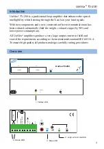
Built-in switched power supply 110-240V AC.
12-24V DC as primary power supply or backup. Connection to 12V DC will
reduce the effect.
Coverage area
170m2 room loop according to IEC 60118-4:2006.
Loop output
Screw terminal
Inputs
Mic
3.5mm, 2-250mV/5kΩ (built-in phantom power)
TV/Ext
SCART, 35mV-10V/5kΩ
In 1
screw terminal, 35mV-10V/5kΩ
In 2
screw terminal, 35mV-10V/5kΩ
In 3
RCA, 35mV/5kΩ


