3
Introduction
Thank you choosing a Univox® product. We hope you will be satisfied!
Univox® P-Loop 2.0 is a compact portable loop system used to enhance speech
intelligibility for hearing aid users with the hearing aid in T-position. It is very easy to use
and can operate in rooms of various sizes up to and including 150 square metres.
All Univox® amplifiers have a very high output current capability resulting in powerful and
secure products fulfilling existing standards, IEC 60118-4.
Please read this user guide carefully before (installation and) use of this product.
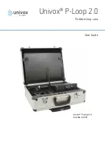
Univox P-Loop 2.0 Portable Loop Case
Univox P-Loop 2.0 portable loop case contains a complete portable loop system with a
built-in amplifier with a 35 meter loop cable on a dispenser and accessories depending
on which loop solution you have chosen. A 15 meters extension cable is also included as
well as the loop test instrument Univox Listener 2.0. Several built-in wireless microphone
options are available. Other accessories that are available for this product are listed in the
section Accessories. The microphone level is preset if you have bought a P-Loop with two
wireless microphones. Please refer to the separate Okayo user guide with addendum for a
more detailed instruction of how to set levels of microphones and amplifier.
We hope that the product will meet your highest expectations!
Setting up the loop
Place the case anywhere along the perimeter of the intended loop. If you do not have
access to a power extension cord, make sure you place the case close enough to the power
outlet for the included power cord to reach. Pull out the loop cable from its dispenser and
place it around the area that you want covered. There is no need to pull out more cable
from the dispenser than is required. Connect both ends of the cable to the amplifier’s
loop terminal marked (8). If needed there is a 15 meter extension cable, making the
maximum coverable area 150m².
Note
. Construction metal can affect the hearing loop to the extent that the loop area needs
to be reduced, alternatively place the cable in a figure 8.


