background image

Universal Chilling Systems, LLC.


Manual

 Model 10

 Air Cooled Chiller 


Operation Manual of Electrical Control of  

UCS Series Industrial Chillers


Contents


1.


Appearance of DM500B 


2.


Face of pages 


3.


User's inquiry operation  


4.


User's set 


5.


Unit Operation 


6.


Trouble disposal 


7.


Settings 


8.


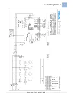
Diagram of electrical connection 


Summary of Contents for UCS Series

Page 1: ...MANUAL FOR AIR COOLED INDUSTRIAL CHILLERS MODEL UCS 10A ...

Page 2: ...ecification 2 Transportation 3 Unit Installation 4 Electrical Installation 5 Commissioning 6 Troubleshooting Operation Manual Contents 1 Appearance of DM500B 2 Face of pages 3 User s inquiry operation 4 User s set 5 Unit Operation 6 Trouble disposal 7 Settings 8 Diagram of electrical connection ...

Page 3: ...ustomers The chillers are applicable to the industries of textile chemicals machinery electronics medicine and health food etc Main components World famous brand refrigeration parts are employed for all products World leading brand compressors High efficient heat exchangers of shell pipe or copper fin type Digital control system Multi Protection devices for over loading high and low pressure phase...

Page 4: ...rrent A 0 99 Safety Protection Device High low voltage protection current overload protection antifreezing protection electronical delay protection Water Pump Power KW 1 1 Current A 2 42 Head M 30 Water Tank Material 304SS Volume L 140 Overall Size Length mm 1810 Width mm 975 Height mm 1730 Overall Unit Weight KG 435 Power KW 12 78 Current A 19 5 Refrigerant Type R407C Notice 1 Normal conditions C...

Page 5: ... 3 Installation 3 1 Positioning The unit must be installed where the air flow is good in door sheltered from raining The space on the top must be larger than 2 meters which is good enough to bring the hot air to environment The space at the air inlet side of the unit must be larger than 1 5 meters that is necessary to normal operation of it A strong water level concrete base with height over 20 cm...

Page 6: ...r or too less water in the pipe It is recommended to fix the water flow switch outside the unit box 4 Electrical Installation 4 1 The UCS Chillers have temperature controller and electrical control box in the unit the work of electrical installation is only to connect the unit to power supply 4 2 In case other control is needed it must be done observing the local electrical standard and rules to g...

Page 7: ...rt b Start order for the air cooled unit chilled water pumps unit c Stop order for the air cooled unit unit chilled water pumps D After start judge the operation status by observing the high and low pressure gauges The normal range of the high pressure is 8 16kg cm2 the low pressure range is 1 5 4kg cm2 a For the air cooled unit observe the rotation direction of the fans if it runs in wrong direct...

Page 8: ...igh 1 Too dirty of the condensers 1 Clean the condensers 2 Too much refrigerant filled 2 Discharge some refrigerant 3 The expansion valve opens too small 3 Adjust the opening of the valve Low pressure too low 1 Too little of the refrigerant 1 Leakage check increase refrigerant and adjust the valve 2 Blockage of the filter 2 Clean or change the filter 3 The expansion valve opens too small 3 Adjust ...

Page 9: ...ooled Chiller Operation Manual of Electrical Control of UCS Series Industrial Chillers Contents 1 Appearance of DM500B 2 Face of pages 3 User s inquiry operation 4 User s set 5 Unit Operation 6 Trouble disposal 7 Settings 8 Diagram of electrical connection ...

Page 10: ...CONTROLLER 9 Air Water Cool 500ATYF02V1002 First page shows welcome count down is shown at the right bottom in reverse color The second page first line shows model and mode second line shows version number of the program at the left and count down is shown at the right bottom in reverse color 2 2 Main Face After the count down iffinished the user s mainface isshown as below TIN l0 C T OUT 5 C SET ...

Page 11: ...how main temp T in T out set temp and running status run time delay stop The reverse color shows the control temp for energy adjustment T in as control temp as fig below T IN means temperature of returning water or air T OUT means temperature of out water or air 3 User s Inquiry Operation Press ENQIRE shows as below TROUBLE LIST TROUBLE HIS This system includes inquiring content as below TROUBLE L...

Page 12: ...rical trouble is 8 with the present trouble placed in front lines Press RESET for 3 S to remove the historical trouble 3 RUN TIME CHECK In inquire page select RUN TIME CHECK by and press OK to enter RUN TIME CHECK show COM1 0 H 0 H COM2 0 H 0 H The accumulated run time will be showed according to the compressor number 4 CLOCK CHECK In inquire page select CLOCK CHECK by and press OK to enter CLOCK ...

Page 13: ... M means the automatic on and off is stopped week time means to start or stop on set time on the set week day Time once means to start or stop on set time each day in the set period If the clock is set as 0 it means no timing in the period If the timing once is selected when the set date is expired press SET the present date will set automatically When select the week timing and timing once at the...

Page 14: ...s below ON 07h 59 m OFF 22h 30 m Select the item to be changed by and press to change the item The data will be kept in memory after the power is off After the change press RETURN to come back to menu of up level ii USE SET In user s page select USE SET by and it will show as below COMP 1 NONE COMP 2 USE The show depends on the number of compressor and heater in RUN SETTINGS SYS SETTINGS and mode ...

Page 15: ...rd is two levels after password of manufacturer s or repairman s is put in it will enter RUN SETTINGS menu as below 1 RUN SETTINGS 2 MODIFY PWD When enter by the repairman s password there will be 2 items in front of the menu 1 RUN SETIINGS 2 MODIFY PWD I RUN SETTINGS In RUN SETTINGS select RUN SETTINGS by and press OK to enter RUN SETTINGS show below 1 SYS SETTINGS 2 SETTINGS 1 There are 10 items...

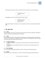
Page 16: ...rer s password only the manufacturer s password can be modified show is below First new password show INPUT5 6BIT PWD The manufacturer s password must be 5 6 Bit after the new password is in the show is below PASSWORD CHECK If the password is the same for both times the show is below PASSWORD ACCEPT PRESS ANY KEY If the check password is not the same as the new password return to new password manu...

Page 17: ...delay time can be changed 6 2 Stop Press the STOP to stop the unit Stop the running compressor time delay stop the cooling fan time delay stop the pump The delayed time can be changed In the delaying period the user s page show time delay after the delay the show is stop 6 3 Trouble and Cause i Compressor breakdown the cause may be compressor overload overheat too high or low pressure ii Unit brea...

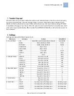
Page 18: ...enu Content AIR WATER 1 SYS SETTINGS SYS AIR WATER W W SYS WATER AIR AIR AIR AIR WATER MODE COOL HEATER H PUMP COOL OUTPUMP NONE CIRCLE RECYCLE NONE COMP NUM Max 4 Min 1 2 ELEC H NUM Max 3 Min 1 0 POINT T IN T OUT T OUT SWITCH SW 1 SW 2 SW 1 Co None None 2 TIME SETTINGS 1 PROTECT Max 255S Min OS 180S CYCLE Max 255S Min OS 120S COOLER_D Max 255S Min OS 15S CHILLER_D Max 255S Min OS 30S ERR DELAY Ma...

Page 19: ...T SET 2 PUMP LACK Normally closed Normally open Normally closed FAN OVERL Normally closed Normally open Normally open FAN OVERH Normally closed Normally open Normally open P_SWITCH Normally closed Normally open Normally closed 10 SENSOR SET IN Use No Use Use OUT Use No Use Use ...

Page 20: ...Universal Chilling Systems LLC 20 Manual Model 10 Air Cooled Chiller ...

Reviews: