background image

UniStream


Unitronics 


10.4” Panel


15.6” 

Panel 


Summary of Contents for UniStream USP-070-B08

Page 1: ... HMI panel The panel provides the CPU s power source The CPU for Panel comprises IO COM Bus connector for interfacing Uni I O Uni COM modules Isolated RS485 and CANbus ports Backup battery HMI Panels Available in different dimensions A high resolution touch screen provides the operator interface for the system and the physical foundation for a PLC HMI I Os all in one controller The DIN rail struct...

Page 2: ...ct should be installed only by qualified personnel Failure to comply with appropriate safety guidelines can cause severe injury or property damage Do not attempt to use this device with parameters that exceed permissible levels Do not connect disconnect the device when power is on Environmental Considerations Ventilation 10mm 0 4 of space is required between the device top bottom edges and the enc...

Page 3: ...liance 3 DIN rail structure Physical support for the CPU for Panel Uni I O and or Uni COM modules 4 12 24VDC power input Connection point for the HMI Panel s power source Connect the Terminal Block supplied with the kit to the end of the power cable 5 2 Ethernet RJ45 ports Support high speed Ethernet communications 6 USB Device Use for application download and direct PC UniStream communication 7 2...

Page 4: ...nsiderations Allocate space for The HMI Panel including the CPU and any modules that will be installed on it Opening the doors of the CPU and modules For exact dimensions please refer to the Mechanical Dimensions shown below HMI Panel Mechanical Dimensions 7 Panel ...

Page 5: ...UniStream Unitronics 5 10 4 Panel 15 6 Panel ...

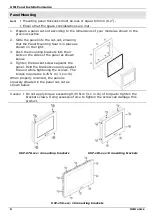
Page 6: ...mounting brackets into their slots on the sides of the panel as shown below 4 Tighten the bracket screws against the panel Hold the brackets securely against the unit while tightening the screws The torque required is 0 35 N m 3 1 in lb When properly mounted the panel is squarely situated in the panel cut out as shown below Caution Do not apply torque exceeding 0 35 N m 3 1 in lb of torque to tigh...

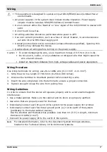
Page 7: ...e from high voltage cables and power equipment Wiring Procedure Use crimp terminals for wiring use 26 12 AWG wire 0 13 mm2 3 31 mm2 1 Strip the wire to a length of 7 0 5mm 0 250 0 300 inches 2 Unscrew the terminal to its widest position before inserting a wire 3 Insert the wire completely into the terminal to ensure a proper connection 4 Tighten enough to keep the wire from pulling free Wiring Gui...

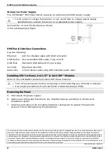
Page 8: ...to support the panel to prevent it from falling during this procedure The information in this documentreflects products at the date of printing Unitronics reserves the right subject to allapplicable laws at any time at itssole discretion and without notice to discontinue or change the features designs materialsand otherspecifications of its products and to either permanently or temporarilywithdraw...

Reviews: