Uni-COM™ CB
Installation
Turn off system power before connecting or disconnecting any module or device.
Use proper precautions to prevent Electro-Static Discharge (ESD).
The module is shipped with its COM module jack covered. To protect the jack from
debris, damage, and ESD, you must leave it covered when not in use.
The final module in a row must have its jack covered.
N
OTE
UAC-CB modules can only be installed onto compatible devices, such as UniStream
PLCs, or connected to other UAC-CB modules.
Installing UAC-CB Modules
N
OTE
Mount on a standard DIN-rail next to a compatible device.
Ensure there is sufficient space to install/uninstall modules.
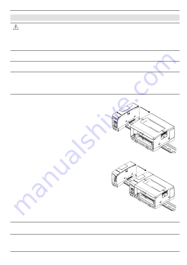
In the first figure below, the module being installed is UAC-CB-01CAN; the second
figure shows a UAC-CB-01RS2 being connected to the UAC-CB-01CAN.
Installing the first module onto the side of the controller:
1. Check the controller to verify that its COM
module jack is not covered.
If the Uni-COM™ CB module the last one in the
configuration, leave the COM jack covered.
2. Push the module onto the DIN-rail until the
clips located at the top and bottom of the unit
have snapped onto the DIN-rail.
3. Slide the module as shown in the accompanying
figure, until the COM module plug is firmly seat
in the other devices’ COM module jack.
Connecting additional modules onto the first:
1. Check the module that is already installed to
verify that its COM jack is not covered.
If the UAC-CB module is to be the last one in
the configuration, do not remove the cover of
its COM jack.
2. Insert the module’s connection plug into the
jack until it is firmly seated.
N
OTE
If you mount vertically, place a DIN-rail stop or end clamp under the final module in
the configuration. This is especially recommended if vibrations are present.
Unitronics
3


