background image

IO-RO8, IO-RO8L   

I / O   E x p a n s i o n   M o d u l e  

1 2 / 0 1


Unitronics Industrial Automation Systems 


Connecting Expansion Modules 

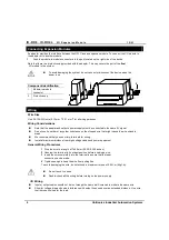
An adapter provides the interface between the OPLC and an expansion module. To connect the I/O module to 
the adapter or to another module: 

Push the module-to-module connector into the port located on the right side of the device. 

Note that there is a protective cap provided with the adapter. This cap covers the port of the 

final 

 I/O module in the system. 


To avoid damaging the system, do not connect or disconnect the device when the  
power is on. 


Component identification 

Module-to-module 
connector 

Protective cap 


1

2


Wiring 

Wire Size  

Use 26-12 AWG wire (0.13 mm 

2

–3.31 mm

2

) for all wiring purposes. 

Wiring Considerations 


Note that the adapter and outputs’ power supply must be connected to the same 0V signal. 


Do not use tin, solder or any other substance on the stripped wire that might cause the wire strand to 
break.  


We recommend that you use crimp terminals for wiring. 


Install at maximum distance from high-voltage cables and power equipment. 

General Wiring Procedures  


Strip the wire to a length of 7±0.5mm (0.250–0.300 inches).  

Unscrew the terminal to its widest position before inserting a wire.  

Insert the wire completely into the terminal to ensure that a proper 
connection can be made. 

Tighten enough to keep the wire from pulling free.  

To avoid damaging the wire, do not exceed a maximum torque of 0.5 N·m (5 kgf·m). 


Do not touch live wires. 


Double-check all the wiring before turning on the power supply. 

I/O Wiring


Input or output cables should not be run through the same multi-core cable or share the same wire. 


Allow for voltage drop and noise interference with output lines used over an extended distance.  Use wire 
that is properly sized for the load. 

Summary of Contents for IO-RO8

Page 1: ... and EMC Only a technician or engineer trained in the local and national electrical standards should perform tasks associated with the electrical wiring of this device Under no circumstances will Unitronics be liable or responsible for any consequential damage that may arise as a result of installation or use of this equipment and is not responsible for problems resulting from improper or irrespon...

Page 2: ... a minimum space of 10mm between the top and bottom edges of the device and the enclosure walls Do not place in water or let water leak onto the unit Do not allow debris to fall inside the unit during installation DIN rail mounting Snap the device onto the DIN rail as shown below the module will be squarely situated on the DIN rail 60mm 3 5mm 14mm 80mm 93mm 44 5mm POWER Screw Mounting The figure o...

Page 3: ...12 01 IO RO8 IO RO8L I O Expansion Module Unitronics Industrial Automation Systems 3 4mm 5 8mm 85mm 80mm 68 4mm 93mm 4mm x2 ...

Page 4: ...st be connected to the same 0V signal Do not use tin solder or any other substance on the stripped wire that might cause the wire strand to break We recommend that you use crimp terminals for wiring Install at maximum distance from high voltage cables and power equipment General Wiring Procedures 1 Strip the wire to a length of 7 0 5mm 0 250 0 300 inches 2 Unscrew the terminal to its widest positi...

Page 5: ...er supply specifications connect the device to a regulated power supply Load 0V N 0V N N 0V N 0V V 24VDC L1 L2 L3 115 230VAC Circuit Protection Device Load L1 L2 L3 115 230VAC V 24VDC 0V N 0V N N 0V N 0V Outputs power supply 0V V POWER Increasing Contact Life Span Both models have 8 relay outputs To increase the life span of these contacts and protect the module from potential damage by reverse EM...

Page 6: ... Isolation By relay Status Indicators O0 to O7 Red LEDs Lit when the corresponding output is active Output current 5A maximum resistive load 1A maximum inductive load Maximum frequency 10Hz Contact protection External precautions required see above Increasing Contact Life Span Outputs power supply IO RO8 Nominal operating voltage 24VDC Operating voltage 20 4 to 28 8VDC Maximum current consumption ...

Page 7: ...n module identification number Adapter The formula below is used to assign addresses for I O modules used in conjuction with the M90 OPLC X is the number representing a specific module s location 0 7 Y is the number of the input or output on that specific module 0 15 The number that represents the I O s location is equal to 32 x 16 y Examples Input 3 located on expansion module 2 in the system wil...

Page 8: ...IO RO8 IO RO8L I O Expansion Module 12 01 8 Unitronics Industrial Automation Systems ...

Reviews: